0 Introduction
With the rapid development of Chinese cities, subways play an increasingly important role in modern urban public transportation. There are many automatic/self-service devices in subway stations, and various failures are inevitable while providing services to passengers. In order to provide efficient and fast services to passengers, subway stations are equipped with passenger assistance service systems.
Wired passenger assistance systems require wiring and are complex to construct, which is not conducive to flexible settings. Wireless passenger assistance systems can be flexibly and conveniently configured and are simple to construct, but they have the disadvantages of insufficient communication distance and weak anti-interference ability. This paper designs a wireless passenger assistance system suitable for the environment in subway stations based on wireless transceiver modules, single-chip microcomputers and repeaters.
1 System Introduction
1.1 System Structure
The subway wireless passenger assistance system is mainly composed of station computers, management terminals, repeaters, and assistance terminals. The station computers and management terminals are installed in the subway station control room, the assistance terminals are installed on equipment or buildings in the subway station that may need passenger assistance services, and the repeaters are installed between the management terminals and the assistance terminals to amplify and transmit wireless signals.
1.2 System Working Principle
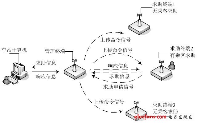
The subway wireless passenger assistance system consists of a station computer installed in the station control room, a management terminal, and multiple assistance terminals distributed throughout the station. When a passenger needs help, he presses the help button on a help terminal. At this time, the help signal light installed on the help terminal changes from dark to always on, indicating that the help signal has been sent. The help signal is transmitted to the management terminal wirelessly. After receiving the help information, the management terminal transmits it to the station computer by wire, and the station computer displays the number of the help terminal that sent the help information. The station manager clicks the help response button on the station computer to respond to the help information. The response information is transmitted to the management terminal by wire and then to the help terminal by wireless. At this time, the help signal light on the help terminal changes from always on to flashing, indicating that the help signal has been responded to. Passengers only need to wait for the staff to come and deal with the problem.
The working principle of the wireless assistance system is shown in Figure 1.

Figure 1 Working principle diagram of wireless passenger assistance system
2 System Design
To meet the design requirements of the wireless passenger assistance system, each part of the system needs to have the following functions:
Station computer: System monitoring virtual instrument, displaying the number, distribution and real-time status of each help terminal; help response button and all response button, responding to the help signal of the corresponding help terminal or all help signals; help clear button and all clear button, clearing the help signal of the corresponding help terminal or all help signals; system status check button, checking whether all help terminals are in normal working condition.
Management terminal: interface module, communicating with the station computer; wireless transceiver module, communicating with the help terminal; microcontroller, controlling the operation of the serial interface and the wireless transceiver module and transmitting and storing relevant information.
Help terminal: Help button, for passengers to use when asking for help; Help indicator light, to prompt passengers whether their help has been responded to; Wireless transceiver module, to communicate with the management terminal; Microcontroller, to control the operation of buttons, indicator lights and wireless transceiver module and store and transmit relevant information.
The hardware design block diagram of the subway wireless passenger assistance system is shown in Figure 2.

Figure 2 Hardware design block diagram of subway wireless passenger assistance system
2.1 Help terminal design
According to the system function requirements, the help terminal uses the wireless transceiver module nRF905. nRF905 is a single-chip RF transceiver launched by Nordic VLSI of Norway. The operating voltage is 1.9~3.6 V, 32-pin QFN package (5 mm×5 mm), and it works in three ISM (industrial, scientific and medical) channels of 433/868/915 MHz. The switching time between channels is less than 650μs. nRF905 consists of a frequency synthesizer, a receiving demodulator, a power amplifier, a crystal oscillator and a modulator. It does not require an external SAW filter, has a ShockBurst working mode, automatically processes the header and CRC (cyclic redundancy check), and uses the SPI interface to communicate with the microcontroller, which is very convenient to configure. In addition, its power consumption is very low. When transmitting with an output power of 10 dBm, the current is only 30 mA, and when working in the receiving mode, the current is 12.5 mA. Built-in idle mode and shutdown mode make it easy to achieve energy saving. nRF905 has 4 working modes, as shown in Table 1. [page]
Table 1 nRF905 working mode

The SPI interface consists of SCK, MISO, MOSI and CSN, which have the functions of SPI clock, SPI output, SPI input and SPI chip select.
The status output interface provides carrier detection output CD, address match output AM, and data ready output DR.
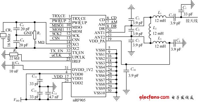
The external circuit of nRF905 is simple and does not require adding too many external devices. Its external schematic diagram is shown in Figure 3.

Figure 3 nRF905 external schematic diagram
The corresponding pins of the single chip microcomputer are connected with the wireless transceiver module nRF905, the help button and the help signal light and control their operation to form a help terminal.
2.2 Management Terminal Design
In addition to the wireless information transmission function of the help terminal, the management terminal also needs to complete the wired information transmission with the computer. Therefore, the management terminal adds a single-chip microcomputer and an interface module on the basis of the help terminal. This article uses the standard RS 232C interface module and the MAX232A chip produced by MAXIM to convert the TTL level of the microcontroller to the standard RS 232C level of the computer serial port.
2.3 Analysis of Repeater Usage
The subway station is a public place with a complex environment, with many buildings and complex interference from various radio frequency devices. The signal sent by the wireless transmission module is difficult to transmit reliably after attenuation and interference. After testing, the reliable communication distance of 10 dBm transmission power is only about 30~40 m, while the subway station is hundreds of meters long. To achieve reliable wireless data communication, the following two solutions can be used:
Solution 1: Realize long-distance data transmission by increasing the power of wireless transmission.
Option 2: Expand the transmission network by adding wireless repeaters to achieve long-distance transmission.
Compared with Solution 1, Solution 2 has the advantages of low power consumption, less impact on human health, and less interference to other equipment in the subway station. Therefore, this paper chooses a repeater to extend the wireless transmission distance.
Calculation method of wireless communication distance in free space propagation: Radio wave propagation when there is infinite vacuum around the antenna is an ideal condition. When radio waves propagate in free space, their energy will not be absorbed by obstacles, nor will it be reflected or scattered. The relationship between communication distance and transmission power, transmission frequency and receiving sensitivity is:
Los=32.44+20lg d+20lgf (1)
Where: Los represents transmission loss, unit: dB; d is the transmission distance, unit: km; f is the carrier frequency, unit: MHz.
It can be seen from formula (1) that the propagation loss (also known as attenuation) of radio waves in free space is only related to the operating frequency f and the propagation distance d. When the transmission loss is constant, the lower the carrier frequency, the longer the transmission distance. Therefore, this paper selects the operating frequency of nRF905 as 433 MHz.
The operating frequency of the wireless transceiver module nRF905 in this article is 433.92 MHz, the transmission power is +10 d13m (10 mW), and the receiving sensitivity is -100dBm. It can be obtained that:
Loss = 110 dB
According to formula (1), the wireless communication distance in free space propagation is d=30km.
This is the ideal transmission distance outdoors without any obstacles or interference sources. In subway stations, the wireless signal strength will be attenuated when encountering factors such as the atmosphere and buildings in the propagation path, which greatly reduces the transmission distance of the wireless signal. When the attenuation is greater than 25 dB, the effective transmission distance of nRF905 will be less than 100m.
During indoor wireless communication, electromagnetic waves will be attenuated by obstacles such as walls, doors and windows. In engineering applications, the attenuation value can be selected according to Table 2.
Table 2 Indoor attenuation table for 433MHz and 868MHz bands

Through actual observation in the subway station, referring to Table 2, it can be concluded that the attenuation of wireless signals in the subway station will be around 25 dB or even more than 25 dB, so at least one repeater is required between the management terminal and the help terminal.
3 Software Design
3.1 Software Anti-interference Design
The environment in subway stations is complex and there are many interference sources, which will affect the accurate transmission of information in the subway wireless passenger assistance system. By controlling the workflow of the system through software, the interference to the system can be effectively reduced. [page]
The working process of the subway wireless assistance system is as follows:
(1) The management terminal sends a command to upload the passenger's help signal to the first help terminal through the wireless transceiver module.
(2) If the first help terminal has a passenger help application, the help terminal sends a help application signal to the management terminal. If the first help terminal has no passenger help application, it returns to the first step and sends a command to upload the passenger help signal to the second help terminal.
(3) After receiving the passenger's request for help from the first help terminal, the management terminal sends an approval signal.
(4) After receiving the approval signal, the first help terminal sends the passenger help information stored in its register to the management terminal.
(5) After receiving the passenger help information from the first help terminal, the management terminal stores it in the register and returns to the first step to send a command signal to upload the passenger help information to the second help terminal.
(6) The management terminal completes a scan of all help terminals and then transmits the passenger help information in its register to the computer through the serial interface.
(7) The help terminal uses the scanning interval to receive the passenger help information sent by the passenger help button and store it in the help terminal register.
3.2 Management Terminal Software Design
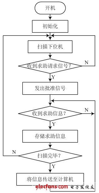
When the management terminal is turned on, it is initialized and then enters the scanning help terminal state. When receiving the passenger help request signal, it sends an approval signal, and after receiving the passenger help information, it stores the passenger help information in the register and continues to scan the next help terminal. After a round of scanning is completed, the passenger help information is transmitted to the computer, and then the next round of scanning begins. Its workflow is shown in Figure 4.

Figure 4 Management terminal workflow diagram
3.3 Help terminal software design
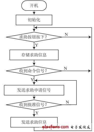
After the help terminal is turned on, it is in the RF receiving mode. The system queries and scans the passenger help button. If it is not pressed, it continues to wait. If the passenger help button is scanned and pressed, the passenger help information is stored in the register and waits for sending. When the command signal sent by the management terminal is received, the passenger help information application signal is sent and the approval signal is waited. After receiving the approval signal from the management terminal, the passenger help information is sent, and then the passenger help button is scanned. The workflow is shown in Figure 5.

Figure 5 Workflow diagram of the help terminal
4 Conclusion
This design analyzes the attenuation of wireless signals in the subway station environment for the wireless transceiver module on the original wireless communication system. It first theoretically proves that the effective transmission distance of the wireless transceiver module in the subway station will be greatly reduced or even less than 100 meters. The feasibility of the theoretical analysis was verified by testing this system in an open environment and a subway station. The station environment has a serious attenuation on the system. This design discussed the solution and finally chose to use a repeater to extend the transmission distance of the wireless transceiver module. This wireless passenger assistance system is also applicable to other public places in complex environments.
Previous article:Three-phase asynchronous motor based on AT89C51
Next article:51 single chip infrared remote control rotating LED digital electronic clock
- Popular Resources
- Popular amplifiers
- Naxin Micro and Xinxian jointly launched the NS800RT series of real-time control MCUs
- How to learn embedded systems based on ARM platform
- Summary of jffs2_scan_eraseblock issues
- Application of SPCOMM Control in Serial Communication of Delphi7.0
- Using TComm component to realize serial communication in Delphi environment
- Bar chart code for embedded development practices
- Embedded Development Learning (10)
- Embedded Development Learning (8)
- Embedded Development Learning (6)
 Professor at Beihang University, dedicated to promoting microcontrollers and embedded systems for over 20 years.
- Intel promotes AI with multi-dimensional efforts in technology, application, and ecology
- ChinaJoy Qualcomm Snapdragon Theme Pavilion takes you to experience the new changes in digital entertainment in the 5G era
- Infineon's latest generation IGBT technology platform enables precise control of speed and position
- Two test methods for LED lighting life
- Don't Let Lightning Induced Surges Scare You
- Application of brushless motor controller ML4425/4426
- Easy identification of LED power supply quality
- World's first integrated photovoltaic solar system completed in Israel
- Sliding window mean filter for avr microcontroller AD conversion
- What does call mean in the detailed explanation of ABB robot programming instructions?
- Europe's three largest chip giants re-examine their supply chains
- Breaking through the intelligent competition, Changan Automobile opens the "God's perspective"
- The world's first fully digital chassis, looking forward to the debut of the U7 PHEV and EV versions
- Design of automotive LIN communication simulator based on Renesas MCU
- When will solid-state batteries become popular?
- Adding solid-state batteries, CATL wants to continue to be the "King of Ning"
- The agency predicts that my country's public electric vehicle charging piles will reach 3.6 million this year, accounting for nearly 70% of the world
- U.S. senators urge NHTSA to issue new vehicle safety rules
- Giants step up investment, accelerating the application of solid-state batteries
- Guangzhou Auto Show: End-to-end competition accelerates, autonomous driving fully impacts luxury...
- (Transfer) Overview of CC2640R2F BLE5.0 Bluetooth Protocol Stack
- [ST NUCLEO-H743ZI Review] Establishing a modbus/TCP slave
- What is a bypass capacitor? What is a decoupling capacitor? What are their differences and connections?
- Proteus simulation micropython example
- Application of Programmable Controller in Automatic Production Line
- MCS-51 series single chip computer instruction system table
- How to avoid PCB electromagnetic interference in switching power supply design
- Industrial Module Technical Data
- 12v to 24v booster circuit diagram, four 12v to 24v booster circuit diagrams, detailed explanation
- Research on Simulation of Spaceborne Synthetic Aperture Radar Data

 UA747HM


 京公网安备 11010802033920号