1. Modulation and Transmission

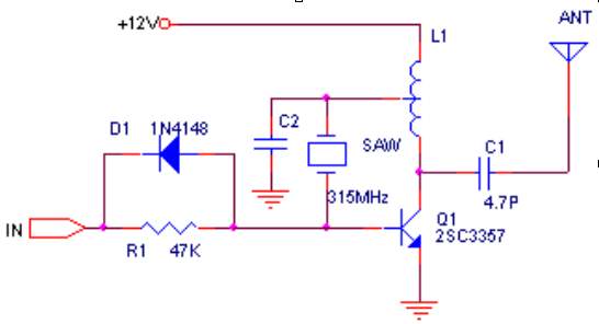
Common analog modulation methods include amplitude modulation, frequency modulation and phase modulation, and common digital modulation methods include frequency shift keying, amplitude shift keying, etc. Although the OOK modulation method has poor performance, the circuit is simple and easy to implement, and the operation is stable. It is widely used in the field of wireless anti-theft and security. For example, this type of circuit is mostly used in car and motorcycle alarms, warehouse doors, and home security systems. See Figure 1. The
early transmitter used an LC oscillation circuit, but this circuit was too affected by distributed parameters, the frequency drift was serious, the stability was poor, and the debugging was complicated. It is now basically not used. Instead, new devices with high stability are waiting, and common ones are surface acoustic wave filters and ceramic resonators.
Surface acoustic wave filters are widely used in high-frequency electronic communications. This filter is small in size, light in weight, the center frequency can be made very high, the relative bandwidth is wide, and it has the frequency selection characteristics of an ideal rectangular coefficient. In addition, this filter can use the same one-sided processing technology as the integrated circuit process, which is simple to manufacture, low in cost, high in remodeling and design flexibility, and can be mass-produced and processed. It is an increasingly widely used filter.
Compared with the crystal oscillator circuit, the surface acoustic wave oscillation circuit is much simpler. The circuit in Figure 1 is a common transmitter circuit. Due to the use of SAW devices, the circuit works very stably. Even if the antenna, SAW device or other parts of the circuit are touched by hand, the transmission frequency will not drift. The effective transmission distance of this circuit can reach more than 200 meters.
The filter formed by the piezoelectric effect of certain ceramic materials is called a ceramic filter. The commonly used ceramic filter is made of lead titanate [Pb (ZrTiO3)].
Compared with other filters, the filter has a simple manufacturing process and can be easily baked into various shapes, which is suitable for the miniaturization of the filter; and it has good heat resistance and moisture resistance and is rarely affected by the outside world. Its QL value is usually several hundred, which is higher than that of LC filters, but lower than that of quartz crystal oscillation. Therefore, when making a filter, the passband is not as narrow as that of a quartz crystal, and the selectivity is worse than that of a quartz crystal filter. At present, ceramic filters are widely used in receivers and other instruments.
2. Reception and demodulation

Common receiving circuits include super-regenerative circuits and super-heterodyne circuits. Super-regenerative circuits are low-cost and power consumption can be as low as about 100uA. The sensitivity of a well-adjusted super-regenerative circuit is similar to that of a super-heterodyne receiver with a high-level amplifier, an oscillator, a mixer, and two intermediate amplifiers. However, the working stability and selectivity of the super-regenerative circuit are relatively poor, so the anti-interference ability is also poor. [page]
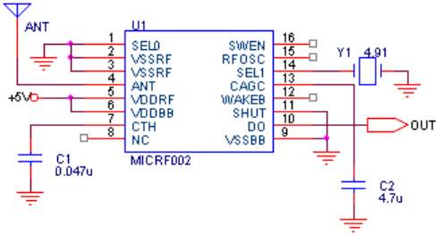
The sensitivity and selectivity of the super-heterodyne circuit can be done very well. Now many companies have produced many receiving super-heterodyne single-chip circuits, which can demodulate the modulated signal with only a few external components. For example, the single-chip integrated circuit receiving and demodulation circuits MICRF001 and MICRF002 launched by Micrel, USA, are demodulation circuits designed for wireless digital communication. With only a few external components, the analog modulated high-frequency signal can be demodulated into a digital signal, which is very simple to use.
4. The
transmitting circuit of the single-chip full-duplex wireless transmission scheme adopts the circuit in Figure 1, and the receiving circuit adopts the circuit in Figure 2. The communication distance is not less than 200M. ICRF002, a single-chip integrated circuit launched by Micrel, USA, can complete reception and demodulation. MICRF002 is an improved version of MICRF001. Compared with MICRF001, it has lower power consumption and a power shutdown control terminal, which can be easily interfaced with a microcontroller. MICRF002 has stable performance and is very simple to use. ICRF002 uses a ceramic resonator. By replacing a different resonator, the receiving frequency can cover 300-440MHz. MICRF002 has two working modes: scanning mode and fixed mode. The receiving bandwidth of scanning mode can reach hundreds of KHz. This mode is mainly used in conjunction with LC oscillation transmitters, because the frequency drift of LC transmitters is large, and the data communication rate in scanning mode is about 2.5KBS per second. The bandwidth of fixed mode is only tens of KHz. This mode is used to match transmitters that use crystal oscillator frequency stabilization, and the data rate can reach 10KBytes per second. The working mode selection is realized through the 16th pin (SWEN) of MICRF002. In addition, the wake-up function can wake up the decoder or CPU to minimize power consumption.
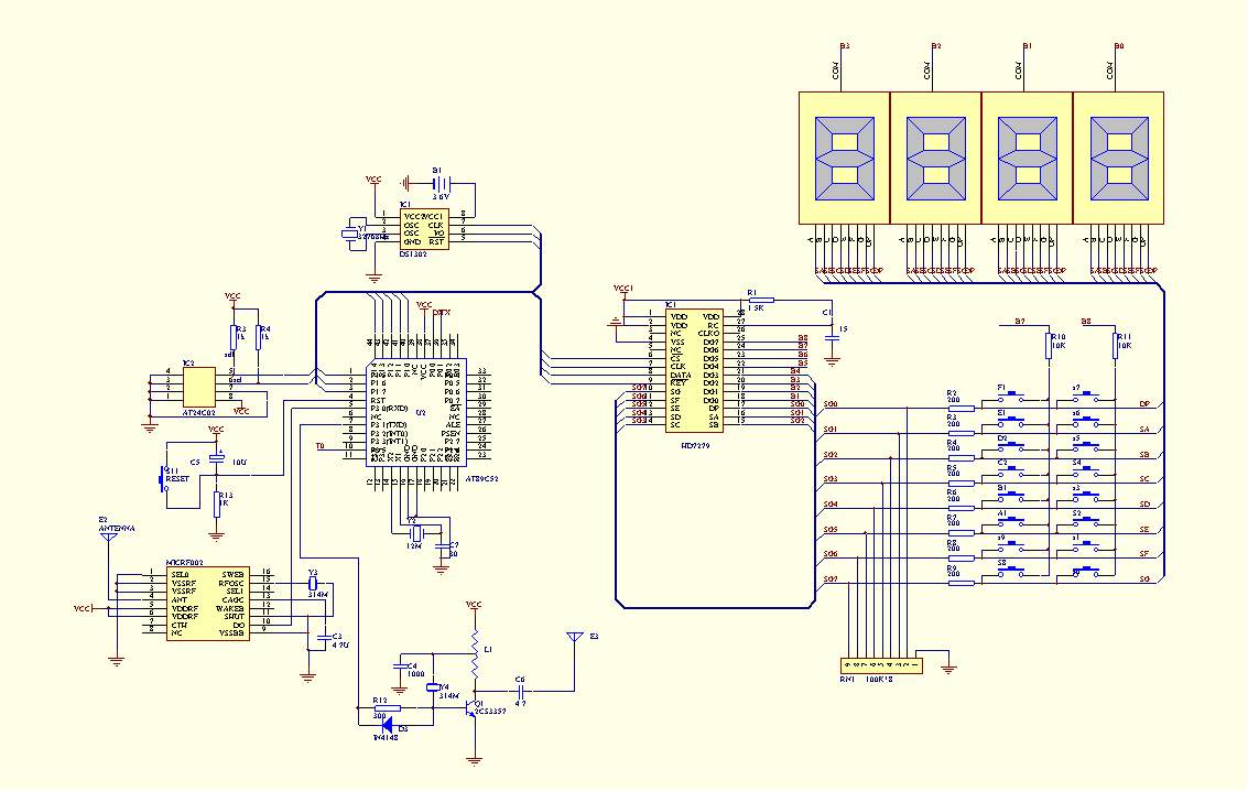
Figure 3 is the main schematic diagram of the 256-channel drip data acquisition system composed of AT89C52. The main machine and the slave can communicate wirelessly in full-duplex serial communication. The serial port transmitter of the single-chip microcomputer is connected to the data input terminal of the circuit in Figure 1, and the data receiver is connected to the data output terminal of the circuit in Figure 2. The communication dial rate of AT89C52 is set to 9.8KB, and T2 works in mode 2 and is used as a dial rate generator. The HD7279 chip is used for display and keyboard management. This chip belongs to the I2C bus device and can manage 64 keyboards and 16-bit digital tubes, or 64-bit LEDs. It is very convenient to use. 
1. The core of wireless SoC (system on chip) - MCU
Our era today is the wireless era. Using RF SoC (system on chip) for wireless communication design is an ideal solution for developing low-cost, low-power wireless communication application systems. The characteristics of RF SoC (system on chip) are:
1) Special design integrates all high-frequency circuits into the internal circuit. There is only a simple filtering circuit from the wireless chip to the antenna, and the system designer does not need to perform any high-frequency circuit design. 2) Special design is used to achieve perfect coordination between the wireless chip, microprocessor and high-frequency lines, minimizing the impact of digital circuits on high-frequency communications. 3) The microprocessor and wireless chip are designed into one, turning it into a wireless single-chip microcomputer. As long as you understand single-chip microcomputers, you can easily complete the design and development of wireless communication functions.
As the core of RF SoC (system on chip), embedded microprocessor needs to be able to perform a large amount of software processing in wireless communication, including error correction, collision prevention, communication protocol processing, etc., especially in complex network systems and the future short-distance, low-power IEEE 802.15.4 standard, the microprocessor needs to undertake a large number of calculation and control functions. In the selection of this microprocessor core, it is necessary to consider:
1/ fast computing power; 2/ extremely low power consumption; 3/ high-efficiency development tools, including compilation/assembly/DEBUG tools; 4/ organic combination with high-frequency wireless transceiver circuits; 5/ application software support.
After comprehensively considering the above factors, most of the chip development companies of wireless SoC (system on chip) have unanimously chosen the 8051 microprocessor core with many years of history as the wireless SoC (system on chip) microprocessor. This is great news for the vast number of MCU engineers and electronic engineers who are preparing to learn to use wireless technology, because in the transition from wired to wireless technology, there is no need to relearn and familiarize yourself with the structure/instruction system/compiler of the MCU; moreover, if you choose the wireless 8051 MCU series development tools of Chengdu Wireless Dragon Communication Technology Co., Ltd., you do not need to refamiliarize yourself with the development tools, but can directly learn the knowledge of wireless communication and quickly enter into the practice of wireless communication.
Previous article:Multi-channel answering device based on single chip microcomputer
Next article:MCU IO expansion program design
Recommended ReadingLatest update time:2024-11-16 15:02


- Popular Resources
- Popular amplifiers
-
 Wireless Sensor Network Technology and Applications (Edited by Mou Si, Yin Hong, and Su Xing)
 -
 Modern Electronic Technology Training Course (Edited by Yao Youfeng)
 -
 Modern arc welding power supply and its control
 -
 Small AC Servo Motor Control Circuit Design (by Masaru Ishijima; translated by Xue Liang and Zhu Jianjun, by Masaru Ishijima, Xue Liang, and Zhu Jianjun)
 Professor at Beihang University, dedicated to promoting microcontrollers and embedded systems for over 20 years.
- Innolux's intelligent steer-by-wire solution makes cars smarter and safer
- 8051 MCU - Parity Check
- How to efficiently balance the sensitivity of tactile sensing interfaces
- What should I do if the servo motor shakes? What causes the servo motor to shake quickly?
- 【Brushless Motor】Analysis of three-phase BLDC motor and sharing of two popular development boards
- Midea Industrial Technology's subsidiaries Clou Electronics and Hekang New Energy jointly appeared at the Munich Battery Energy Storage Exhibition and Solar Energy Exhibition
- Guoxin Sichen | Application of ferroelectric memory PB85RS2MC in power battery management, with a capacity of 2M
- Analysis of common faults of frequency converter
- In a head-on competition with Qualcomm, what kind of cockpit products has Intel come up with?
- Dalian Rongke's all-vanadium liquid flow battery energy storage equipment industrialization project has entered the sprint stage before production
- Allegro MicroSystems Introduces Advanced Magnetic and Inductive Position Sensing Solutions at Electronica 2024
- Car key in the left hand, liveness detection radar in the right hand, UWB is imperative for cars!
- After a decade of rapid development, domestic CIS has entered the market
- Aegis Dagger Battery + Thor EM-i Super Hybrid, Geely New Energy has thrown out two "king bombs"
- A brief discussion on functional safety - fault, error, and failure
- In the smart car 2.0 cycle, these core industry chains are facing major opportunities!
- The United States and Japan are developing new batteries. CATL faces challenges? How should China's new energy battery industry respond?
- Murata launches high-precision 6-axis inertial sensor for automobiles
- Ford patents pre-charge alarm to help save costs and respond to emergencies
- New real-time microcontroller system from Texas Instruments enables smarter processing in automotive and industrial applications
- NUCLEO_G431RB Review (3) Oversampling 16-bit ADC
- ESP32 internal structure diagram
- SDIO connection to TF card initialization failed
- This Wednesday's award-winning live broadcast: 5G conformance testing and device acceptance testing
- Is it "reasonable..." to fly a kite made of your own photo?
- Battery Management System BMS Technical Data Transfer
- X-NUCLEO-IKS01A3 sensor test based on STM32F401RE development board 2 LPS22HH pressure sensor
- stm32 usb cdc communication
- [ATmega4809 Curiosity Nano Review] Unboxing
- How to burn MSBL format firmware

 Wireless Sensor Network Technology and Applications (Edited by Mou Si, Yin Hong, and Su Xing)


 京公网安备 11010802033920号