1 Pin arrangement and main features of P87LPC767
P87LPC767 is an OTP series microcontroller launched by PHILIPS Semiconductor Company. It adopts a 20-pin package and can provide high-speed and low-speed crystal oscillator and RC oscillator modes. The clock can also be selected through software programming. This microcontroller has a wide operating voltage range, and the output mode of the I/O port can be selected through control register programming. It contains a digital watchdog circuit and I2C bus. Its two internal analog comparators can form an 8-bit A/ The D and D/A converters have both power-on reset detection and under-voltage reset detection functions, and the driving current of its I/O port can reach 20mA. The P87LPC767 adopts the 80C51 acceleration processing structure. The instruction execution speed is twice that of the standard 80C51 MCU. The temperature range is -40~+85℃. The microcontroller itself has excellent electromagnetic compatibility and inherits the PHILI PS semiconductor’s low power consumption and undecipherability and other characteristics. Figure 1 shows the pin diagram of the P87LPC767 microcontroller. The main features of this chip are as follows:
●Using 20-pin DIP and SO packages to meet the needs of different users

●The clock frequency can reach up to 20MHz. In addition to multiplication and division instructions, its accelerated execution time can be increased to 300~600ns.
●Contains 4-channel multi-channel 8-bit A/D converter. When the oscillation frequency fosc is 20MHz, the conversion time is only 9.3μs.
●Extremely wide voltage applicable range. When used for digital functions, the operating voltage range is 2.7~6.0V.
●Contains 4k bytes of OTP program memory and 128 bytes of RAM. There is also a 32Byte user code area that can be used to store serial codes and set parameters.
●Contains two 16-bit timers/counters. Each timer can be set to trigger the corresponding port output mode when it overflows. It contains 2 analog comparators internally.
●With full-duplex universal asynchronous receive/transmit (UART) and I2C communication interface, and has 2 external interrupt inputs and 8 keyboard interrupt inputs as well as 4 interrupt priority levels.
●With internal digital watchdog circuit, the watchdog timer uses an on-chip independent oscillator to work. Since no external components are required, it can be used for oscillator failure detection. There are 8 selection methods for the watchdog overflow time.
●Has two reset modes: low level and low voltage. In low-level reset, it can be reset by on-chip power-on without external components; in low-voltage reset, one of the two preset voltages can be selected to reset, and the system can be safely shut down when power is lost. . In addition, it can also be configured as an interrupt source.
●The programmable I/O port output mode has quasi-bidirectional port, open-drain output port, pull-up and input port modes, and the Schmitt trigger input mode can be used to control the port line output conversion speed to reduce EMI. All I/O lines have 20mA drive capability.

●It can be programmed online through serial EPROM, and there is a 2-digit E-PROM security code to prevent the program from being read out.
●With low power consumption function, when the voltage is 3.3V and the frequency is 20kHz~100kHz, the quiescent current is only 9~44μA. It also has two power-saving modes: idle and power-down, and has a power-down wake-up function.
2 Main functions of P87LPC767
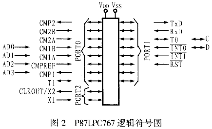
The P87LPC767 itself has a variety of functions. Figure 2 shows the logic symbol diagram of the device.
2.1 Enhanced MCU
Since the P87LPC767 microcontroller adopts the 80C51 acceleration processing structure, the running speed is 2 times that of the standard 80C51. This means that the performance of the P87LPC767 at 10MHz is the same as that of the standard 80C5 1The performance is the same when using 20MHz. One of its machine cycles consists of 6 oscillation cycles, and the execution time of most instructions is 6 or 12 oscillation cycles. Therefore, the standard 80C51 MCU timing can be selected through the internal register to turn one machine cycle into 12 oscillation cycles.
2.2 Configurable simulation functions
P87LPC767 integrates 1 A/D converter, 2 analog comparators and 2 D/A converters. Therefore, in order to improve performance and reduce power consumption during use, the internal registers PTOAD and The corresponding bits of PXM1 and PXM2 are used to turn off the digital signal input (except DAC output pin) and output function of the analog function pin.
2.3 A/D converter
The P87LPC767 has a four-channel 8-bit A/D converter inside. Four P0 ports can be selected as inputs for A/D conversion. The power supply and reference voltage of its A/D conversion share VCC and VSS with the MCU. The minimum operation of A/D conversion is 3V. The connection method of A/D converter is shown in Figure 3.

The A/D converter includes a 4-analog multiplexer selector and an 8-bit successive approximation ADC. The A/D also has a ratio potentiometer to ensure the monotonicity of the DAC. The A/D converter can be controlled by the special function register ADCON, and the A/D can be enabled by setting the ENADC bit, and the A/D conversion can be started by setting the ADCS bit. After the A/D conversion is completed, the ADCS bit is cleared, the interrupt flag ADCI is set, and sampling is performed through query or interrupt mode. At the same time, when the conversion is completed, the result is placed in DAC0. The ideal A/D conversion result (V) is as follows:
V=(VIX-VSS)×256/(VDD-VSS) (round the result)
2.4 I2C bus interface
The I2C bus of P87LPC767 transmits information between the bus and the device through two lines (SDA and SCL). When transmitting information, the bus has the characteristics of bidirectional transmission of data between master and slave devices, serial addressing of slave devices, generation of response bits after each byte is transmitted, and arbitration when multiple hosts transmit at the same time to avoid data conflicts on the bus.
The I2C bus system includes an I2C bus hardware that simplifies software drivers. In addition to the necessary bus arbitration, framing error detection, clock stretching, and bus timeouts, cyclic polling and interrupts are available through a one-bit interface to synchronize the software.
2.5 Interruption
P87LPC767 has four priority interrupt structures, which provides great flexibility for P87LPC767's multi-interrupt source processing. The P87LPC767 can support up to 13 interrupt sources. Any interrupt source can be individually enabled or disabled by setting or clearing the corresponding bits in IEN0 and IEN1. Each interrupt source can be achieved by clearing or setting the corresponding bit in IP0, IP0H, IP1, IP1H (00 is the lowest, 11 is the highest). Peer interrupts can be handled through the query sequence of the arbitration queue.
P87LPC767 allows some or all pins of port 0 to be enabled as keyboard interrupts, and this can be achieved by setting the corresponding bit in the internal special function register KBI. When the KBI interrupt function is turned on, any enabled pin pulled low will set the keyboard interrupt flag (KBF) in the AUXRI register. Since human operation has mechanical delays in time resolution accuracy and key switch closure, the KBI feature is usually used to poll port 0 of the interrupt service program in turn to determine which key was pressed, and sometimes even determine whether Wakes the processor from low-power mode.

3 Applications of P87LPC767
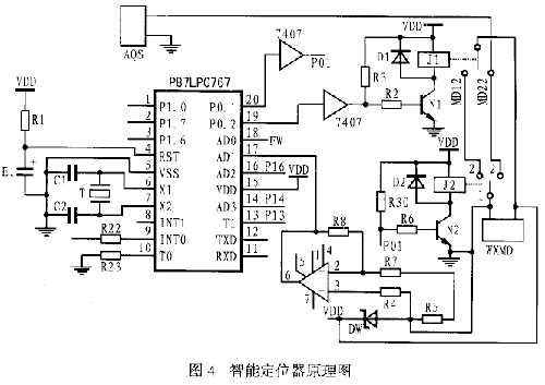
According to the P87LPC767 microcontroller, it has strong anti-interference ability, wide temperature adaptability range, contains high-quality A/D converter, can provide enhanced MCU, can set the analog function, powerful keyboard interrupt function and micro-power consumption, etc. Combined with the technical requirements of the intelligent positioning controller, the author designed a two-wire micro-power intelligent positioner based on the P87LPC767 microcontroller to replace the positioner with a nozzle-baffle force balance structure, thus improving the automation level of the system and reducing the cost. Reduces the work intensity of operating personnel. The circuit schematic diagram of this two-wire micro-power intelligent positioner is shown in Figure 4.
The positioner uses the 4-20mA signal provided by the control room safety barrier (AQS) to provide power to the positioner through a voltage stabilization and signal conversion circuit. It also provides input signals to the positioner and sends them to the AD1 port. When the position signal (FW) detected by the position detector is sent to the AD0 port, it is sampled and processed by the microcontroller. At the same time, the output control signal is sent to the multiplexing switch. Finally, the pneumatic execution can be controlled by the micromotor (WXMD). mechanism to achieve position control.
4 Conclusion
Since the power supply of the positioner is provided by the output current of the safety barrier, its load capacity is limited. In order to make the micro motor and multiplex switch of the positioner operate reliably, in addition to selecting low-power consumption devices, the number of peripheral chips should also be minimized. Quantity, because the P87LPC767 has an internal A/D converter, comparator and extremely strong I/O port driving capability, and has good temperature characteristics. Therefore, it can be used to solve some technical problems and greatly improve reliability.
Previous article:P87LPC767 microcontroller and its application in micro-power intelligent positioner
Next article:Application of light touch switch circuit in AVR microcontroller
Recommended ReadingLatest update time:2024-11-17 02:30

 Professor at Beihang University, dedicated to promoting microcontrollers and embedded systems for over 20 years.
- Innolux's intelligent steer-by-wire solution makes cars smarter and safer
- 8051 MCU - Parity Check
- How to efficiently balance the sensitivity of tactile sensing interfaces
- What should I do if the servo motor shakes? What causes the servo motor to shake quickly?
- 【Brushless Motor】Analysis of three-phase BLDC motor and sharing of two popular development boards
- Midea Industrial Technology's subsidiaries Clou Electronics and Hekang New Energy jointly appeared at the Munich Battery Energy Storage Exhibition and Solar Energy Exhibition
- Guoxin Sichen | Application of ferroelectric memory PB85RS2MC in power battery management, with a capacity of 2M
- Analysis of common faults of frequency converter
- In a head-on competition with Qualcomm, what kind of cockpit products has Intel come up with?
- Dalian Rongke's all-vanadium liquid flow battery energy storage equipment industrialization project has entered the sprint stage before production
- Allegro MicroSystems Introduces Advanced Magnetic and Inductive Position Sensing Solutions at Electronica 2024
- Car key in the left hand, liveness detection radar in the right hand, UWB is imperative for cars!
- After a decade of rapid development, domestic CIS has entered the market
- Aegis Dagger Battery + Thor EM-i Super Hybrid, Geely New Energy has thrown out two "king bombs"
- A brief discussion on functional safety - fault, error, and failure
- In the smart car 2.0 cycle, these core industry chains are facing major opportunities!
- Rambus Launches Industry's First HBM 4 Controller IP: What Are the Technical Details Behind It?
- The United States and Japan are developing new batteries. CATL faces challenges? How should China's new energy battery industry respond?
- Murata launches high-precision 6-axis inertial sensor for automobiles
- Ford patents pre-charge alarm to help save costs and respond to emergencies
- Design of intelligent charging lighting control system based on MSP430 single chip microcomputer
- The world's first Pi-powered satellite
- STM32L151C8T6 cannot enter serial port interrupt
- How to simulate the sound control circuit in Proteus? Please guide me, thank you.
- Moderator Rewards Announcement for March and April 2019
- Switching Circuit
- [RVB2601 Creative Application Development] My Guitar Environmental Protector - Automatic Dry and Humidity Regulator
- 【NXP Rapid IoT Review】 NO2. Experience Sharing of Mobile App BLE Control Development Kit
- What is the role of Zigbee wireless data transmission module in wireless personal area network?
- The TMS320F28377S LaunchPad development kit uses CCS8 to program and control LED lights. Why do problems always occur when compiling?

 西门子S7-12001500 PLC SCL语言编程从入门到精通 (北岛李工)


 京公网安备 11010802033920号