Inductor is a component that we use for a long time in transformer design. Its main function is to convert electrical energy into magnetic energy and then store it. It should be noted that although the structure of the inductor is similar to that of a transformer, it has only one winding. This article mainly introduces the principle of the inductive DC-DC booster, and this article is of basic nature, suitable for those who do not understand the characteristics of inductors but are interested in boosters. Some of the principle knowledge in the article can be found on the Internet, so I will not elaborate on it here.
To fully understand the principle of inductive boost, we must first know the characteristics of inductance, including electromagnetic conversion and magnetic energy storage. These two points are very important because all the parameters we need are derived from these two characteristics.
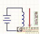
First, let's look at the following picture:

As you all know, the picture above is an electromagnet, where a battery energizes a coil. Some people may wonder, what is there to analyze with such a simple picture? We are going to use this simple picture to analyze what happens when it is powered on and off.
The coil (hereinafter referred to as "inductor") has a characteristic - electromagnetic conversion. Electricity can be converted into magnetism, and magnetism can be converted back into electricity. When the power is turned on, the electricity will be converted into magnetism and stored in the inductor in the form of magnetism. When the power is turned off, the magnetism will be converted into electricity and released from the inductor.
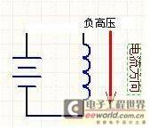
Now let's look at the picture below to see what happens when the power goes out:

As I said before, the magnetic energy in the inductor will be converted back into electricity when the inductor is powered off. However, the question is: how can the magnetism be converted into electricity when the circuit is broken and the current has nowhere to go? It's simple. High voltage will appear at both ends of the inductor! How high can the voltage be? Infinitely high, until it breaks through any medium that blocks the flow of current.
Here we understand the second characteristic of inductance - the voltage-boosting characteristic. When the loop is disconnected, the energy in the inductor will be converted back into electricity in the form of infinitely high voltage. How high the voltage can be increased depends only on the breakdown voltage of the dielectric variable.
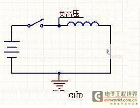
Now let's summarize the above content:
The following is a positive voltage generator. If you keep flipping the switch, you can get an infinitely high positive voltage from the input. How high the voltage rises depends on what you connect to the other end of the diode so that the current has a place to go. If nothing is connected, the current has nowhere to go, so the voltage will rise high enough to break down the switch, and the energy will be consumed in the form of heat.
 Then there is the negative pressure generator. You keep flipping the switch and you can get an infinitely high negative voltage from the input.

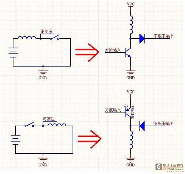
The above are all theories. Now let's take a look at some actual electronic circuit diagrams to see what the "minimum system" of the positive/negative pressure generator looks like:
You can clearly see the evolution, the circuit just replaced the switch with a triode. Don't underestimate these two diagrams, in fact, all switching power supplies are derived from the combination of these two diagrams, so it is very important to master these two diagrams.

Finally, let's talk about magnetic saturation. What is magnetic saturation?
From the above background, we know that inductors can store energy and preserve it in the form of magnetic fields, but how much can it store? What happens when it is full?
1. How much is stored: The "maximum magnetic flux" parameter is used for this purpose. Obviously, the inductor cannot store energy infinitely. The amount of energy it stores is determined by the product of voltage and time. For each inductor, this is a constant. Based on this constant, you can calculate how high a frequency an inductor must operate at to provide N volts and megaamperes of power.
2. What happens when the inductor is fully charged? This is the problem of magnetic saturation. After saturation, the inductor loses all the characteristics of an inductor and becomes a pure resistor, dissipating energy in the form of heat.
Previous article:Analysis of the current status and development trend of LED power supply industry
Next article:Analysis and development trend of LED driving technology without power supply integrated light source
Recommended ReadingLatest update time:2024-11-16 14:24


- Popular Resources
- Popular amplifiers
-
 New Energy Vehicle Detection and Diagnosis Experiment (Edited by Mao Caiyun, Zhou Xien, and Long Jiwen)
 -
 Design of an adaptive constant on-time buck DC-DC converter with high efficiency and low power consumption
 -
 Research on design technology of high-efficiency step-up DC-DC converter with wide load range
 -
 Switching power supply design based on charge pump DC-DC converter
- MathWorks and NXP Collaborate to Launch Model-Based Design Toolbox for Battery Management Systems
- STMicroelectronics' advanced galvanically isolated gate driver STGAP3S provides flexible protection for IGBTs and SiC MOSFETs
- New diaphragm-free solid-state lithium battery technology is launched: the distance between the positive and negative electrodes is less than 0.000001 meters
- [“Source” Observe the Autumn Series] Application and testing of the next generation of semiconductor gallium oxide device photodetectors
- 采用自主设计封装,绝缘电阻显著提高!ROHM开发出更高电压xEV系统的SiC肖特基势垒二极管
- Will GaN replace SiC? PI's disruptive 1700V InnoMux2 is here to demonstrate
- From Isolation to the Third and a Half Generation: Understanding Naxinwei's Gate Driver IC in One Article
- The appeal of 48 V technology: importance, benefits and key factors in system-level applications
- Important breakthrough in recycling of used lithium-ion batteries
- Innolux's intelligent steer-by-wire solution makes cars smarter and safer
- 8051 MCU - Parity Check
- How to efficiently balance the sensitivity of tactile sensing interfaces
- What should I do if the servo motor shakes? What causes the servo motor to shake quickly?
- 【Brushless Motor】Analysis of three-phase BLDC motor and sharing of two popular development boards
- Midea Industrial Technology's subsidiaries Clou Electronics and Hekang New Energy jointly appeared at the Munich Battery Energy Storage Exhibition and Solar Energy Exhibition
- Guoxin Sichen | Application of ferroelectric memory PB85RS2MC in power battery management, with a capacity of 2M
- Analysis of common faults of frequency converter
- In a head-on competition with Qualcomm, what kind of cockpit products has Intel come up with?
- Dalian Rongke's all-vanadium liquid flow battery energy storage equipment industrialization project has entered the sprint stage before production
- Allegro MicroSystems Introduces Advanced Magnetic and Inductive Position Sensing Solutions at Electronica 2024
- Car key in the left hand, liveness detection radar in the right hand, UWB is imperative for cars!
- After a decade of rapid development, domestic CIS has entered the market
- Aegis Dagger Battery + Thor EM-i Super Hybrid, Geely New Energy has thrown out two "king bombs"
- A brief discussion on functional safety - fault, error, and failure
- In the smart car 2.0 cycle, these core industry chains are facing major opportunities!
- The United States and Japan are developing new batteries. CATL faces challenges? How should China's new energy battery industry respond?
- Murata launches high-precision 6-axis inertial sensor for automobiles
- Ford patents pre-charge alarm to help save costs and respond to emergencies
- New real-time microcontroller system from Texas Instruments enables smarter processing in automotive and industrial applications
- Capacitive touch sensing solution based on STM8 series 8-bit general-purpose MCU
- TI Bluetooth 4.0 chip cc2540
- How to use the 5V output of a microcontroller to drive a 24V solenoid valve?
- RLC analog circuit design
- msp430 PWM period calculation
- 150 examples of amateur production of communication circuits
- This is how to use the LM2596S-ADJ DC-DC step-down chip
- STM32F103 project of LPS33HW
- [#Ren Zhengfei responds to hot topics#: We cannot narrowly think that loving Huawei means loving Huawei phones]
- Here is the camera information on the national competition list

 New Energy Vehicle Detection and Diagnosis Experiment (Edited by Mao Caiyun, Zhou Xien, and Long Jiwen)


 京公网安备 11010802033920号