In recent years, the application of high-brightness LED has developed rapidly, especially in signboards and traffic lights. For automotive applications, LED is also very attractive. Long life, shock resistance, high efficiency, and good control of light sources are all its advantages. Of course, compared with incandescent lamps, LEDs require drive circuits. In addition, automotive electrical systems are powered by lead-acid batteries, which are charged by mechanically driven AC generators. This type of battery is suitable for incandescent lamps, but not for LEDs. Therefore, it is very necessary to design a drive circuit with good voltage stabilization performance and low noise.
In theory, LED light output is related to the drive current and has nothing to do with the power supply voltage. For the lowest demand application, if the power supply voltage is stable, a resistor can limit the current. It is worth noting that for this simplest application circuit, the LED shows a self-stabilizing characteristic to a certain extent. That is, if the temperature rises, the light output of the LED decreases, but at the same time its forward voltage drop also decreases, which increases the drive current, thereby compensating for the decrease in light output at higher temperatures.
Unfortunately, the range of automotive power supply is very large, between 8V-18V, and the peak voltage can reach tens of volts. In addition, the high-brightness LED drive current is large, which will generate a lot of heat on the resistor, complicating the heat dissipation design.
A relatively simple solution is to use a linear buck regulator (Figure 1). D1 is a Zener diode, and the current through the LED is set to VD1/RSET. D2 performs humidity compensation on the base diode. This circuit still has energy loss and resistor heat dissipation problems. For low-current LEDs, especially when the forward voltage drop of the LEDs in series is slightly lower than the power supply voltage, this circuit is a cost-effective solution.

Figure 1 Simple current stabilization circuit
In most cases, switching power supplies provide a better electrical solution. As the name implies, switching power supplies work in a switch, charging the RLC circuit in one cycle; in the next cycle, the stored energy is used to drive the load. This type of circuit has a very high efficiency, generally reaching more than 90%. Switching regulators can increase voltage, decrease voltage, and generate voltages of opposite polarity, which linear regulators do not have.
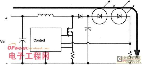
The simplest switching regulator is the buck regulator shown in Figure 2. The voltage difference between the input voltage and the LED voltage charges the inductor L, and the current increases accordingly. When the current reaches a preset value, the control circuit turns off the series transistor, forming an alternating current in the LED path. Note that in LED drive applications, the switching regulator circuit controls the peak value of the current.
This value is set by a programmable IC or external components. The current value is also defined by the sense resistor on the drain of the FET switch. The current flowing through the LED of the buck regulator is continuous, but alternating, while it is discontinuous for the power supply, which will have a certain impact on the operation of the power supply and increase the noise on the power line.

Figure 2 Buck-type switching current stabilization circuit If the power supply voltage is lower than the sum of the voltages of all LEDs in series, a boost regulator should be used. The boost regulator (Figure 3) must control both current and voltage, and the circuit is relatively complex. The boost regulator also has serious interference problems under high current conditions. Therefore, the most stable and safest LED driver can be a combination of boost and buck. A boost regulator can drive several buck regulators in parallel. In this way, the power supply is faced with a good-performance boost regulator, while the load end is a high-current output buck regulator.

Figure 3 Boost switch current stabilization circuit
All switching power supplies will generate noise. Voltage regulators can increase the operating frequency and use large capacitors to filter at the output. LED power supplies are current-stabilizing types. To reduce noise, the following measures must be taken:
Reduce the operating frequency.
· The switching transistor should be placed in the center area of the circuit board.
Fast recovery diode.
Do not form a current loop in the LED area.
Shorten cables and printed circuit board traces.
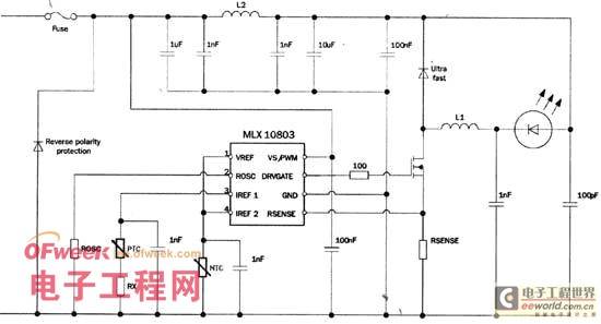
In addition to the above measures, the new solution also helps reduce the noise of the driving power supply. Melexis' MLX10801 and MLX10803 LED drivers use a pseudo-random switching frequency generator to reduce electrical noise. Figure 4 is a circuit example for low-noise applications, which meets the Level 5 standard of CISPR25, where CISPR is the French abbreviation for the International Special Committee on Radio Interference. The working inductor L1 should be determined based on the switching frequency and LED current. To facilitate user design, the company also provides a software and Excel spreadsheet for selecting ROSC, RSET and RSENSE.

Figure 4 MLX10803 application example
For the circuit in Figure 4, the switching frequency should be lower than 150KHz. If the LED current is between 0.5-1A, L1 and L2 are 100?H. The noise is broadband, so the filter capacitor adopts a combination of large and small solutions. Diode D1 is the main source of high-frequency noise and should be carefully selected. When the power supply voltage is lower than 100V, a Schottky diode can be used.
The light output intensity of GaAs and GaAsP LEDs is closely related to the junction temperature. For example, if the LED outputs 100% at 25°C, it will only be 80% at 80°C. The driver is equipped with a temperature slope compensation circuit. In fact, a PTC or NTC resistor can solve the problem, using the temperature coefficient of the PTC to balance the light output of the LED. In order to protect the LED, an NTC resistor can be added to the input end of the device when the temperature is higher than 80°C.
Previous article:How to Correctly Select LED Driver Power Supply
Next article:Analysis of Passive Drive (PMOLED) Technology
Recommended ReadingLatest update time:2024-11-16 22:31


- Popular Resources
- Popular amplifiers
- MathWorks and NXP Collaborate to Launch Model-Based Design Toolbox for Battery Management Systems
- STMicroelectronics' advanced galvanically isolated gate driver STGAP3S provides flexible protection for IGBTs and SiC MOSFETs
- New diaphragm-free solid-state lithium battery technology is launched: the distance between the positive and negative electrodes is less than 0.000001 meters
- [“Source” Observe the Autumn Series] Application and testing of the next generation of semiconductor gallium oxide device photodetectors
- 采用自主设计封装,绝缘电阻显著提高!ROHM开发出更高电压xEV系统的SiC肖特基势垒二极管
- Will GaN replace SiC? PI's disruptive 1700V InnoMux2 is here to demonstrate
- From Isolation to the Third and a Half Generation: Understanding Naxinwei's Gate Driver IC in One Article
- The appeal of 48 V technology: importance, benefits and key factors in system-level applications
- Important breakthrough in recycling of used lithium-ion batteries
- Innolux's intelligent steer-by-wire solution makes cars smarter and safer
- 8051 MCU - Parity Check
- How to efficiently balance the sensitivity of tactile sensing interfaces
- What should I do if the servo motor shakes? What causes the servo motor to shake quickly?
- 【Brushless Motor】Analysis of three-phase BLDC motor and sharing of two popular development boards
- Midea Industrial Technology's subsidiaries Clou Electronics and Hekang New Energy jointly appeared at the Munich Battery Energy Storage Exhibition and Solar Energy Exhibition
- Guoxin Sichen | Application of ferroelectric memory PB85RS2MC in power battery management, with a capacity of 2M
- Analysis of common faults of frequency converter
- In a head-on competition with Qualcomm, what kind of cockpit products has Intel come up with?
- Dalian Rongke's all-vanadium liquid flow battery energy storage equipment industrialization project has entered the sprint stage before production
- Allegro MicroSystems Introduces Advanced Magnetic and Inductive Position Sensing Solutions at Electronica 2024
- Car key in the left hand, liveness detection radar in the right hand, UWB is imperative for cars!
- After a decade of rapid development, domestic CIS has entered the market
- Aegis Dagger Battery + Thor EM-i Super Hybrid, Geely New Energy has thrown out two "king bombs"
- A brief discussion on functional safety - fault, error, and failure
- In the smart car 2.0 cycle, these core industry chains are facing major opportunities!
- The United States and Japan are developing new batteries. CATL faces challenges? How should China's new energy battery industry respond?
- Murata launches high-precision 6-axis inertial sensor for automobiles
- Ford patents pre-charge alarm to help save costs and respond to emergencies
- New real-time microcontroller system from Texas Instruments enables smarter processing in automotive and industrial applications
- Project Management (Passive Components)
- Help: Using SHT75, extending the wiring, the data read is 65535
- Detailed graphic analysis of the relationship between power supply PCB layout and EMC (LLC)
- LMV358 no output
- 【Silicon Labs Development Kit Review】+ Get familiar with the development environment and download the breathing light routine
- EEWORLD University ---- Interoperability of isolated CAN FD nodes
- How are soft-start circuits for power supplies, motors, and other equipment usually implemented?
- EEWORLD University Hall----Live Replay: TI Wireless Product Update: Wi-Sun Standard Helps Smart City Construction
- TI automotive solution puzzle, do you dare to challenge it?
- [SAMR21 new gameplay] 8. Serial communication-1

 Siemens PLC Project Tutorial
 LED Cube Code
 ESP32-S3 source code


 京公网安备 11010802033920号