LCD display technology
Liquid crystal displays (LCDs) appeared on calculators in 1973. The first LCD was embedded with seven-segment calligraphy and painting, allowing numbers to be displayed. The next generation of LCD was launched in 1980. It is a dot-matrix display. In addition to displaying numbers, it also has characters and graphics, such as a simple monochrome computer display or the popular "electronic pet". pool. These matrix designs are controlled by activating rows and columns of pixels in the matrix, replacing the need for an independent control line for each pixel. By the late 1980s, color filters were successfully embedded in LCD designs. Since the beginning, all generations of products have focused on improvements in screen size, display weight, energy efficiency, viewing angles, etc.

Figure 1. By applying voltage to control the vertical alignment of liquid crystal molecules, light can pass along the molecules.
Despite continuous improvements, the basic operation of the LCD display remains the same. The pixel array of an LCD display is constantly illuminated by a backlight, and the long-lasting light eliminates a type of flicker found in CRTs (phosphor dots pulsating and flashing with each refresh cycle). Instead, LCD pixels are sandwiched between two glass plates with vertical grooves on each other, as shown in Figure 1. These pits are aligned with the liquid crystal to form channels that allow backlight to pass to the front of the screen. The amount of light transmitted depends on the orientation of the liquid crystal. and proportional to the applied voltage.
The upper and lower plates are polarized perpendicular to each other. A voltage between the two plates adjusts the liquid crystal in a twist mode to match the polarization of each plate. Light from the backlight passes through the calibrated liquid crystal. On the contrary, when the liquid crystal is not adjusted, the light is blocked, and the adjustment component is proportional to the applied voltage and serves as photometric control.

Table 1. Lists pixel array sizes for various video formats
The outer plate is a color filter (RGB). Red, green, and blue areas (each called a sub-pixel) are included in each pixel. The color areas related to each primary color are separately addressed, so full colors can be displayed. and luminosity. The number of pixels determines the clarity of the display. Table 1 lists the pixel array sizes for various video formats. Note that the number of pixel array sizes does not translate directly to aspect ratio because the pixels are not typically square.
Causes of LCD flickering

Figure 2. Visual example of flicker in an LCD display.
(a) (Left) LCD optimized flicker. (b) (right picture) LCD has excessive flickering
The flicker on an LCD display is different from that of a CRT in that the LCD flicker itself appears faded rather than pulsating light. As shown in Figures 2a and 2b, Figure 2a shows that the LCD display has been adjusted to reduce flickering, while Figure 2b shows that the LCD has excessive flickering. This is because the LCD's refresh rate is as high as 300Hz. 
Figure 3. Circuit of a single LCD image
Figure 3 shows a circuit for driving a single LCD pixel. The gate voltage is charged as a switch and is generally amplified to become -5V to 20V. The voltage on the video source generally ranges from 0V to 10V, providing the brightness information that appears on the pixel. Below the pixel is the backplane that is connected to the screen, and the voltage at this node is Vcom.
Although this layout method works, it reduces the screen life, assuming that the Vcom voltage is grounded. The voltage on the pixel varies from 0V to 10V, assuming an average of 5V. This results in a significant DC voltage across each pixel. This DC voltage causes charge storage. In the long term, due to the electrode plating on the pixels
The presence of ionic impurities deteriorates the pixels, which is the cause of image retention. It is common in old TFT-LCD panels where the color fades.
The structure of the LCD screen is symmetrical (Figure 1). Both positive and negative voltages can be used to adjust the liquid crystal. One way to make full use of this is to move the common voltage to the midpoint of the video signal (5V) , the video signal now swings up and down on the common voltage (Vcom), thus creating a "net-zero effect" on the pixels. This net-zero effect that occurs on the liquid crystal eliminates burn-in and image retention issues. This technology requires a compromise in clarity because the video signal runs 5V to full brightness instead of 10V.

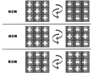
Figure 4. LCD pixel phase distribution in alternating frames for three inversion modes: frame inversion, line inversion, and point inversion.
To achieve a net-zero effect on the display, various inversion modes can be used across the entire LCD frame (Figure 4). The simplest type is Frame Inversion. Under this driving method, every pixel on the screen is inverted in each subsequent frame. Frame inversion creates a net zero effect on pixels relative to time. The other two methods are inversions incorporated into each frame. Line inversion alternates the phase on each horizontal line. The alternating pattern of line inversion applied to the common phase of a pair of horizontal lines (rather than a single line) is called line-paired inversion. Dot inversion inverts the phase of each adjacent pixel like a chess board. All three methods also create a net-zero effect on pixels relative to time. The inversion mode is selected by the factory and embedded in the driver circuit. In all cases, each display frame is alternately inverted.
The Vcom voltage needs to be placed exactly at the midpoint of the video signal to avoid flickering. When trying to explain why a display flickers, assume it's because of the way the screen is made. Vcom is set at 5.5V. If the video signal swings between 0V and 10V, the full-scale voltage will be different in each field. The full-scale voltage in one field will be 4.5V, while in another field the full-scale voltage will be 5.5V. , this difference in full-scale voltage will be converted into a photometric difference, so flickering occurs.

Figure 5. Measuring screen flicker using light sensor EL7900
Figure 5 shows the difference in light intensity of the picture with and without flicker. The light-colored waveform has a larger DC level, and the recorded picture has no flicker. An EL7900 photosensitive sensor was used for this measurement. The light sensor converts light intensity into current, and the greater the current, the greater the voltage deflection produced on the oscilloscope.
In order for everyone to understand these results, you first need to know that there are two types of LCD screens: "white" screens and "black" screens. The white screen in the relaxed state (no voltage is applied to the liquid crystal) allows light to pass through the liquid crystal, while the black screen blocks all light in the relaxed state. When the voltage applied to the liquid crystal increases, the liquid crystal rotates. This blocks more light (as in the case of a white screen) or allows more light to pass (as in the case of a black screen). The screen test is a white screen, so the greater the voltage applied to the LCD, the darker the screen. If the Vcom voltage is set exactly in the middle (no flicker), then the average AC voltage is zero and the picture will still be at its brightest point. If the Vcom voltage is not in the middle. Then, the AC voltage will be higher as a result, so the screen brightness will be darker.
The fading in Figure 2b is caused by an imbalance in the Vcom voltage causing an incorrect voltage on the liquid crystal, not an overall light intensity issue.
How to eliminate LCD flickering

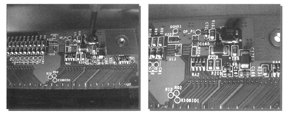
Figure 6. (a) (left) Using a mechanical potentiometer to adjust VCOM. (b) (right picture) Use a digitally controlled potentiometer to adjust VCOM.
Since each LCD display has structural changes, the optimal Vcom voltage value will differ from LCD to LCD. Therefore, the original equipment manufacturer must adjust each factory display to eliminate this flicker. For small displays, the visual backplane is a low-impedance ground, so a potentiometer can be added as a common voltage adjustment. Generally speaking, using a mechanical potentiometer requires additional work hours. For small screens
This is acceptable, even on a large screen. Low accuracy and easily damaged during assembly, requiring complete assembly replacement. For screens over 19 inches, the bottom plate can no longer be regarded as a single low-impedance node. Multiple corrections need to be made at different locations on the screen. There may be as many as five local compensation networks, four at the corners and one in the middle. In this case ∶ Digitally Controlled Potentiometer (DCP) can automatically handle this processing for manufacturers, which is necessary for large screens that cannot be adjusted manually. Figures 6a and 6b show a mechanical versus numerically controlled potentiometer solution.

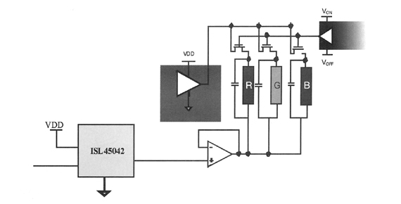
Figure 7. Application circuit of DCP software programmable VCOM
The conversion from mechanical potentiometer to DCP and system implementation is very simple. Figure 7 shows the application circuit of DCP software programming Vcom driver. ISL45042 is a current output type, non-volatile DCP that can operate on AVDD up to 20V. ISL45042 Using dual-wire, upper and lower interfaces, it is an extremely accurate 7-bit device with 128 levels of resolution. The required Vcom value can be stored in the EEPROM on the board. The voltage range of digital circuits is from 2.25V to 3.6V. This allows it to interface with many controllers used today. Analog power is applied to the analog resistor ladder and can operate from 4.5V to 20V. This is an important feature for small screens that generally require less than 10V analog power and large screens that require greater than 15V analog power. The DCP output voltage is buffered and fed to the Vcom bus via the EL5111 amplifier (180mA output current).
Contrary to popular belief, LCD displays do flicker, but a simple potentiometer adjustment can reduce this effect because LCD flickering occurs on offsets in the common voltage, not on the refresh signal.
As LCDs become more popular and screen sizes continue to increase, manual adjustment at a single point on the backplane is no longer feasible. Using the ISL45042 DCP and EL5111 Vcom buffers, automatic Vcom offset correction can be performed at multiple points on the backplane. The effect is more obvious.
Previous article:Design of Chinese character LCD intelligent display module based on 51 microcontroller
Next article:Application of universal optical fiber isolation driver in high-power IGBT
Recommended ReadingLatest update time:2024-11-17 00:17
- Popular Resources
- Popular amplifiers
-
 A review of learning-based camera and lidar simulation methods for autonomous driving systems
 -
 Semantic Segmentation for Autonomous Driving: Model Evaluation, Dataset Generation, Viewpoint Comparison, and Real-time Performance
 -
 Motor Control and Learning (Markus Latash, Francis Lestienne)
 -
 Computer Control Systems (Compiled by Tian Hong)
- MathWorks and NXP Collaborate to Launch Model-Based Design Toolbox for Battery Management Systems
- STMicroelectronics' advanced galvanically isolated gate driver STGAP3S provides flexible protection for IGBTs and SiC MOSFETs
- New diaphragm-free solid-state lithium battery technology is launched: the distance between the positive and negative electrodes is less than 0.000001 meters
- [“Source” Observe the Autumn Series] Application and testing of the next generation of semiconductor gallium oxide device photodetectors
- 采用自主设计封装,绝缘电阻显著提高!ROHM开发出更高电压xEV系统的SiC肖特基势垒二极管
- Will GaN replace SiC? PI's disruptive 1700V InnoMux2 is here to demonstrate
- From Isolation to the Third and a Half Generation: Understanding Naxinwei's Gate Driver IC in One Article
- The appeal of 48 V technology: importance, benefits and key factors in system-level applications
- Important breakthrough in recycling of used lithium-ion batteries
- Innolux's intelligent steer-by-wire solution makes cars smarter and safer
- 8051 MCU - Parity Check
- How to efficiently balance the sensitivity of tactile sensing interfaces
- What should I do if the servo motor shakes? What causes the servo motor to shake quickly?
- 【Brushless Motor】Analysis of three-phase BLDC motor and sharing of two popular development boards
- Midea Industrial Technology's subsidiaries Clou Electronics and Hekang New Energy jointly appeared at the Munich Battery Energy Storage Exhibition and Solar Energy Exhibition
- Guoxin Sichen | Application of ferroelectric memory PB85RS2MC in power battery management, with a capacity of 2M
- Analysis of common faults of frequency converter
- In a head-on competition with Qualcomm, what kind of cockpit products has Intel come up with?
- Dalian Rongke's all-vanadium liquid flow battery energy storage equipment industrialization project has entered the sprint stage before production
- Allegro MicroSystems Introduces Advanced Magnetic and Inductive Position Sensing Solutions at Electronica 2024
- Car key in the left hand, liveness detection radar in the right hand, UWB is imperative for cars!
- After a decade of rapid development, domestic CIS has entered the market
- Aegis Dagger Battery + Thor EM-i Super Hybrid, Geely New Energy has thrown out two "king bombs"
- A brief discussion on functional safety - fault, error, and failure
- In the smart car 2.0 cycle, these core industry chains are facing major opportunities!
- The United States and Japan are developing new batteries. CATL faces challenges? How should China's new energy battery industry respond?
- Murata launches high-precision 6-axis inertial sensor for automobiles
- Ford patents pre-charge alarm to help save costs and respond to emergencies
- New real-time microcontroller system from Texas Instruments enables smarter processing in automotive and industrial applications
- [NXP Rapid IoT Review] + NXP Rapid IoT Prototyping Kit Data Collection
- Special considerations for HUADA MCU design
- [NXP Rapid IoT Review] + Unboxing and Getting to Know the Kit
- Advantages of WiFi6 compared with other WiFi
- KiCad (5.0.2) calculator tool
- The problem of resistance and capacitance
- R1
- What is Python? Why is it so popular?
- Is GaN a key technology for 5G?
- GD32L233C-START development board review 1: Unboxing, development board interface function analysis and project creation in KEIL development environment

 A review of learning-based camera and lidar simulation methods for autonomous driving systems


 京公网安备 11010802033920号