Digital voltmeters have been designed and developed in many types and styles. Traditional digital voltmeters have their own characteristics. They are suitable for manual measurement on site. To complete remote measurements and further analyze and process the measurement data, traditional digital voltmeters cannot complete it. However, a digital voltmeter based on PC communication can not only complete the transmission of measurement data, but also use the PC to process the measurement data. Therefore, this type of digital voltmeter has characteristics that traditional digital voltmeters cannot match in terms of function and practical application, which makes its development and application have good prospects.
Overall design of new digital voltmeter
The measurement voltage type of this new digital voltmeter is DC, and the measurement range is -5~+5V. The whole machine circuit includes: MCU minimization design of data acquisition circuit, MCU and PC interface circuit, MCU clock circuit, reset circuit, etc. The lower computer uses AT89S51 chip, and the A/D conversion uses AD678 chip. Communicates with the PC through the RS232 serial port and transmits the measured DC voltage data. The whole system circuit is shown in Figure 1.
The principle of data acquisition circuit
In the design of the microcontroller data acquisition circuit, the circuit design was minimized, that is, no additional logic devices were used as interface circuits, and the microcontroller's operation of the AD678 conversion chip was realized.
AD678 is a high-end, multi-functional 12-bit ADC. Since it has built-in sample and hold, high-precision reference power supply, internal clock and three-state buffered data output, it only requires a few external components. It constitutes a complete data acquisition system, and an A/D conversion only takes 5ms.
In the circuit application, AD678 adopts synchronous working mode, and the 12-bit digital output adopts 8-bit operation mode, that is, the 12-bit converted digital quantity is read twice, first reading the high 8 bits, and then reading the low 4 bits. Bit. According to the timing relationship, when the chip selects /CS=0, the conversion terminal /SC changes from high to low once, and the A/D conversion can be started once. Then query the conversion end end /EOC to see if the conversion has ended. If it ends, the output enable /OE will become low and the output will be valid. The reading of 12-bit digital quantity requires controlling the high byte valid end/HBE, reading the high byte first, and then reading the low byte. The entire A/D operation is roughly the same, and it is adjusted in actual development and application.

Figure 1 Circuit diagram of digital voltmeter
Since the bipolar input mode of AD678 is used in the circuit, the input voltage range is -5~+5V. According to the formula Vx=10(V)/4096*Dx, the measured voltage Vx value can be calculated. In the formula, Dx is the 12-bit digital value after conversion of the measured DC voltage.
Design of RS232 interface circuit
The interface circuit between AT89S51 and PC uses chip Max232. Max232 is a chip launched by Texas Instruments (TI) that is compatible with the RS232 standard. The device contains 2 drivers, 2 receivers and a voltage generator circuit providing TIA/EIA-232-F levels. The Max232 chip has a level conversion function to match the TTL level of the microcontroller with the RS232 level of the PC.
The RS232 interface for serial communication uses a 9-pin serial port DB9. Serial port data transmission can be realized as long as there are receiving data pins and sending pins: the receiving pins and sending pins of the same serial port are directly connected with wires, two serial ports are connected or one serial port and multiple serial port connection. In the experiment, timer T1 is used as the baud rate generator, and its initial counting value X is calculated according to the following formula:
Baud rate =  *(T1 overflow rate)
=  *
*
The serial communication baud rate is set to 1200b/s, while SMOD=1, fosc=6MHz, and the initial counting value X=0f3H is calculated. Just load it into TL1 and TH1 during programming.
In order to facilitate observation, when each time the voltage is measured and data is collected, when the microcontroller has a port output, it is indicated by a light-emitting diode (LED).
software programming
The software programs mainly include: data acquisition program of the lower computer, visual interface program of the upper computer, and serial communication program between the microcontroller and PC. The single-chip microcomputer is programmed with C51 language, and the operation display interface of the host computer is visually programmed with VC++6.0. During the serial communication debugging process, with the help of the "Serial Port Debugging Assistant" tool, this tool can be effectively used to improve the efficiency of the entire system.
Microcontroller programming
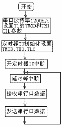
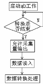
The data collection communication main program flow of the lower computer microcontroller is shown in Figure 2, the interrupt subroutine is shown in Figure 3, and the collection subroutine is shown in Figure 4. With the help of WAVE2000 emulator for programming simulation and debugging of microcontroller, this system has an integrated ISP simulation and debugging environment.

Figure 2 Microcontroller communication main program collection
In the acquisition program, the programming operation of the microcontroller must fully comply with the timing specification requirements of AD678. In actual development, it must be continuously debugged. Finally, the .bin file generated by the successful debugging of the lower computer is solidified into the Flash unit of AT89S51.


Figure 3 Interrupt service subroutine Figure 4 Collection subroutine
Human-computer interface programming
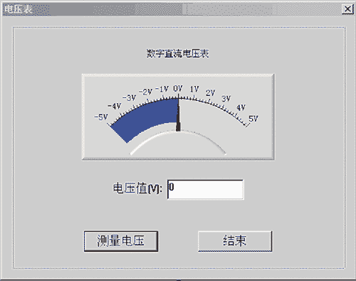
Open VC++6.0 and create a dialog-based MFC application. Serial communication is implemented using the MSComm control. Other operations will not be described here. Programming implements a good human-machine interface. The operation interface of the digital DC voltmeter is shown in Figure 5. By running the Windows program programmed with VC++6.0, the entire prototype function can be realized.
Functional results
According to the working principle and implementation plan mentioned above, the functions of the entire prototype have been well realized in practice, and all indicators have met the pre-design requirements. The circuit works stably, each measurement is accompanied by LED lighting instructions, and the visual interface display is also normal.

Figure 5 Human-machine interface of digital voltmeter
AD678 conversion accuracy is 12 bits, and its resolution is 1/4096. This provides a guarantee for the high accuracy of the entire machine system. In order to improve the measurement accuracy, the AD678's own calibration circuit is used, which makes its A/D conversion accuracy higher. In the actual measurement, the measurement accuracy of the whole machine reached 0.8%.
Previous article:Design of portable multifunctional real-time physiological parameter monitor
Next article:Design of vehicle-mounted compaction real-time detection system based on DSP
- Keysight Technologies Helps Samsung Electronics Successfully Validate FiRa® 2.0 Safe Distance Measurement Test Case
- From probes to power supplies, Tektronix is leading the way in comprehensive innovation in power electronics testing
- Seizing the Opportunities in the Chinese Application Market: NI's Challenges and Answers
- Tektronix Launches Breakthrough Power Measurement Tools to Accelerate Innovation as Global Electrification Accelerates
- Not all oscilloscopes are created equal: Why ADCs and low noise floor matter
- Enable TekHSI high-speed interface function to accelerate the remote transmission of waveform data
- How to measure the quality of soft start thyristor
- How to use a multimeter to judge whether a soft starter is good or bad
- What are the advantages and disadvantages of non-contact temperature sensors?
- Innolux's intelligent steer-by-wire solution makes cars smarter and safer
- 8051 MCU - Parity Check
- How to efficiently balance the sensitivity of tactile sensing interfaces
- What should I do if the servo motor shakes? What causes the servo motor to shake quickly?
- 【Brushless Motor】Analysis of three-phase BLDC motor and sharing of two popular development boards
- Midea Industrial Technology's subsidiaries Clou Electronics and Hekang New Energy jointly appeared at the Munich Battery Energy Storage Exhibition and Solar Energy Exhibition
- Guoxin Sichen | Application of ferroelectric memory PB85RS2MC in power battery management, with a capacity of 2M
- Analysis of common faults of frequency converter
- In a head-on competition with Qualcomm, what kind of cockpit products has Intel come up with?
- Dalian Rongke's all-vanadium liquid flow battery energy storage equipment industrialization project has entered the sprint stage before production
- Allegro MicroSystems Introduces Advanced Magnetic and Inductive Position Sensing Solutions at Electronica 2024
- Car key in the left hand, liveness detection radar in the right hand, UWB is imperative for cars!
- After a decade of rapid development, domestic CIS has entered the market
- Aegis Dagger Battery + Thor EM-i Super Hybrid, Geely New Energy has thrown out two "king bombs"
- A brief discussion on functional safety - fault, error, and failure
- In the smart car 2.0 cycle, these core industry chains are facing major opportunities!
- The United States and Japan are developing new batteries. CATL faces challenges? How should China's new energy battery industry respond?
- Murata launches high-precision 6-axis inertial sensor for automobiles
- Ford patents pre-charge alarm to help save costs and respond to emergencies
- New real-time microcontroller system from Texas Instruments enables smarter processing in automotive and industrial applications
- Testing solutions for redundant link networks
- Key wireless technologies for 5G systems
- [NXP Rapid IoT Review] + Rapid IoT App Running Error
- How to Design an RF Power Amplifier: The Basics
- What is the principle of touch switch?
- What is jitter and phase noise?
- [Shanghai Hangxin ACM32F070 development board + touch function evaluation board evaluation] + OLED screen display driver
- Tailing Micro B91 Development Kit Burning Pitfalls Record
- Antai Testing - Sharing of Maintenance Experience of Tektronix AFG3021 Arbitrary Signal Generator
- Interrupt vectors for ARM (Cortex-M3)

 【Follow me Season 2 Episode 1】-Mission Code (Adafruit Circuit Playground Express Development Board)
 【Follow me Season 2 Episode 1】Source code
 5962R9863702QPA


 京公网安备 11010802033920号