[Future Testable] Series 2: Basic Research and Performance Research Test Scheme of Memristor Unit
Memristor is called memristor in English, represented by the symbol M. It constitutes four basic passive circuit devices with resistance R, capacitance C and inductance L. It is the link between magnetic flux and charge. It has the performance of both resistance and storage. It is a new generation of high-speed storage unit, usually called resistive random access memory (RRAM).
Important application areas of memristors that have attracted much attention include: nonvolatile memory, logic computing, and brain-inspired neuromorphic computing. These three completely different but interrelated technical routes provide a feasible route for developing a new computing architecture that integrates information storage and processing and breaks through the bottleneck of the traditional von Neumann architecture.
While memristor research continues to achieve new results, multifunctional coupling devices based on memristors have also become a hot topic for researchers. These new coupling devices include: magnetic coupling devices, optical coupling devices, superconducting coupling devices, phase change memristor devices, ferroelectric coupling devices, etc.
1. Basic research and testing of memristors
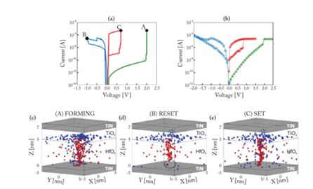
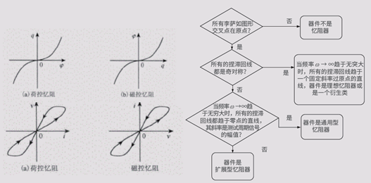
Memristor research can be divided into three stages: basic research, performance research, and integrated research. This research method is applicable to resistive random access memory (RRAM), phase change memory (PCM), and ferroelectric random access memory (FeRAM). The basic research stage of memristors mainly studies the material system and physical mechanism of memristors, characterizes the parameters of memristors, and classifies memristors through hysteresis loops. The basic research tests of memristors include: DC characteristics, AC characteristics, and pulse characteristics tests.
Memristor DC characteristic test is usually combined with Forming, mainly testing the memristor DC VI curve, and using it to deduce important memristor parameters such as SET/RESET voltage/current, HRS, LRS, etc., which can be scanned unidirectionally or bidirectionally. Memristor AC characteristics mainly test the pinch hysteresis loop, which is the key to identifying the type of memristor. Memristor pulse testing can effectively reduce the impact of Joule heat accumulated in DC testing, and can also be used to study the impact of heat on device performance. As memristor characterization technology is developing towards extremes, the demand for picosecond pulse erasure and signal capture is becoming increasingly strong.
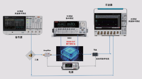
Tektronix Memristor Basic Research Test Solution
Cost-effective testing solution

Extreme Characterization Test Solution


Tektronix solution features:
Various configuration options to meet different customer needs
Tektronix China has a local R&D team to meet customers’ customized testing needs
Tektronix partners provide full hardware system integration
Many leading memristor R&D units adopt Tektronix test solutions
2. Memristor performance research and testing
The memristor performance research and testing process is as follows:

The performance study of non-volatile memory is achieved by testing the number of cycles or endurance and data retention of the memristor. In the cycle number and endurance test, the resistance test is usually completed by a semiconductor parameter tester with a pulse function. Due to the large number of samples to be tested and the long time consumption, programming is required for automated testing. In extreme characterization cases, the SET/RESET pulse is generated by a high-speed arbitrary wave generator.
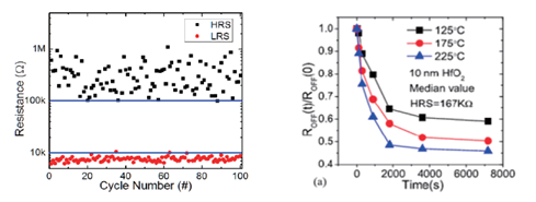
If memristors are used in neuron research, in addition to the number of erases and writes and the data retention time, their performance tests also require synaptic resistance dynamics testing. Synaptic plasticity is the neurobiological basis of brain memory and learning, and there are many forms. According to the length of memory, it can be divided into short-term plasticity (STP) and long-term plasticity (LTP), among which short-term plasticity includes paired pulse depression (PPD), paired pulse facilitation (PPF), and posttetanic potentiation (PTP). In addition, there are some other plasticities, such as: discharge rate dependent plasticity (SRDP), discharge time dependent plasticity (STDP), etc., which are the basis for synapses to process neural signals and neural calculations.
The conductive state of the memristor can be used to represent the change of synaptic weight. By changing the shape, frequency, duration and other parameters of the stimulation pulse voltage, the characteristics of the neural stimulation signal corresponding to different synaptic functions can be simulated. Measuring the transient current can understand the dynamic process of resistance change and obtain the regulation method of neural morphological characteristics. Similar to the cycle number and endurance test, it is necessary to program the semiconductor parameter tester with pulse function or high-speed arbitrary wave generator to generate the corresponding pulse sequence for automated testing.

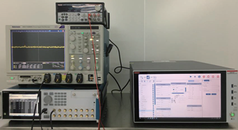
Tektronix Memristor Performance Research Test Solution
Tektronix solution features:
Various configuration options to meet extreme surface testing needs
The cost-effective solution can be upgraded to a low-dimensional array test solution
Tektronix China has a local R&D team to meet customers’ customized testing needs
Many leading memristor R&D units adopt Tektronix test solutions
Previous article:[Practical Tips] How to measure ultra-low bias currents using commercial-grade lab equipment
Next article:How to measure AC and DC current with a multimeter
Recommended ReadingLatest update time:2024-11-16 23:46


- Keysight Technologies Helps Samsung Electronics Successfully Validate FiRa® 2.0 Safe Distance Measurement Test Case
- From probes to power supplies, Tektronix is leading the way in comprehensive innovation in power electronics testing
- Seizing the Opportunities in the Chinese Application Market: NI's Challenges and Answers
- Tektronix Launches Breakthrough Power Measurement Tools to Accelerate Innovation as Global Electrification Accelerates
- Not all oscilloscopes are created equal: Why ADCs and low noise floor matter
- Enable TekHSI high-speed interface function to accelerate the remote transmission of waveform data
- How to measure the quality of soft start thyristor
- How to use a multimeter to judge whether a soft starter is good or bad
- What are the advantages and disadvantages of non-contact temperature sensors?
- Innolux's intelligent steer-by-wire solution makes cars smarter and safer
- 8051 MCU - Parity Check
- How to efficiently balance the sensitivity of tactile sensing interfaces
- What should I do if the servo motor shakes? What causes the servo motor to shake quickly?
- 【Brushless Motor】Analysis of three-phase BLDC motor and sharing of two popular development boards
- Midea Industrial Technology's subsidiaries Clou Electronics and Hekang New Energy jointly appeared at the Munich Battery Energy Storage Exhibition and Solar Energy Exhibition
- Guoxin Sichen | Application of ferroelectric memory PB85RS2MC in power battery management, with a capacity of 2M
- Analysis of common faults of frequency converter
- In a head-on competition with Qualcomm, what kind of cockpit products has Intel come up with?
- Dalian Rongke's all-vanadium liquid flow battery energy storage equipment industrialization project has entered the sprint stage before production
- Allegro MicroSystems Introduces Advanced Magnetic and Inductive Position Sensing Solutions at Electronica 2024
- Car key in the left hand, liveness detection radar in the right hand, UWB is imperative for cars!
- After a decade of rapid development, domestic CIS has entered the market
- Aegis Dagger Battery + Thor EM-i Super Hybrid, Geely New Energy has thrown out two "king bombs"
- A brief discussion on functional safety - fault, error, and failure
- In the smart car 2.0 cycle, these core industry chains are facing major opportunities!
- The United States and Japan are developing new batteries. CATL faces challenges? How should China's new energy battery industry respond?
- Murata launches high-precision 6-axis inertial sensor for automobiles
- Ford patents pre-charge alarm to help save costs and respond to emergencies
- New real-time microcontroller system from Texas Instruments enables smarter processing in automotive and industrial applications
- Application Guide for HB6296 High Voltage and High Current Charging Management Chip for 2-10 Cells Lithium Battery 24V Lead Acid
- Schematic diagram - Can the push-pull circuit in this place be omitted?
- ADI differential amplifier drives up to 380MHz for 3G/4G and Wimax applications
- [Synopsys IP Resources] Flexible interface IP solutions based on USB4 for edge AI
- [Help] I'm trying to build a NAS for my own use with a Raspberry Pi. Can anyone tell me if it's useful?
- Today at 10:00 AM Award-winning live broadcast: nanoPower technology: Extending battery life and improving sensor performance
- I want a master to look at the circuit diagram of the X-ray machine and explain the circuit a little bit.
- A pit of STM32 standard USB library (V2.2.1)
- CodeBug Hands-on Learning 1 - Unboxing
- HP laptop battery is swollen, where can I get a new one?

 Test solutions in the 800V electric drive development and design process (Tektronix China)


 京公网安备 11010802033920号