What is a Multimeter?
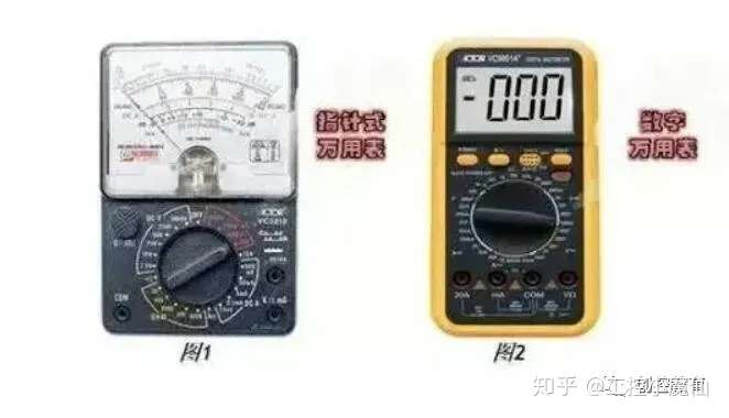
A multimeter is also called a multi-purpose meter, a three-purpose meter, or a multiplexer. Multimeters are divided into pointer multimeters and digital multimeters.
It is a multifunctional, multi-range measuring instrument. Generally, a multimeter can measure DC current, DC voltage, AC current, AC voltage, resistance and audio level, etc. Some can also measure AC current, capacitance, inductance and some parameters of semiconductors.
How to view the operation panel?
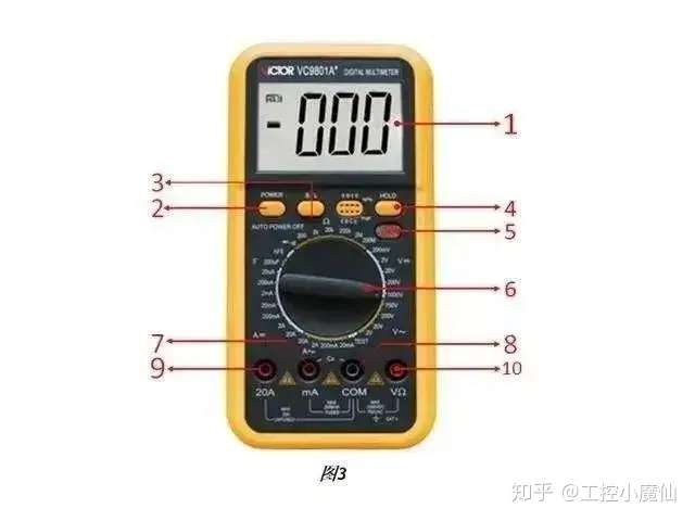
1. LCD display (displays the value measured by the instrument)
2. POWER switch: Turn the power on and off.
3. B/L backlight switch: Turn on the backlight and it will automatically turn off after about 10 seconds.
4. HOLD switch: Press this key, the current measured value of the meter will be kept on the LCD and the "HOLD" symbol will appear. Press it again and the "HOLD" symbol will disappear, exiting the hold function state.
5. Live wire identification indicator light.
6. Rotary switch: used for the function status and range of the meter;
7. Current test socket less than 2A;
8. Common ground: positive socket of test accessory;
9. 20A current test socket;
10. Voltage, resistance and frequency sockets;
Safety Symbols
(1) Dangerous voltage exists

(2) The operator must refer to the instruction manual

(3) Grounding

Introduction to the main functions of the multimeter
DC voltage detection
AC voltage detection
DC current detection
AC current detection
Resistance Ω detection
Diode/continuity detection
Capacitance C detection
FireWire Identification TEST
DC voltage detection
(1) Insert the black test lead into the "COM" jack and the red test lead into the "VΩ" jack (as shown in Figure 4);
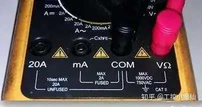
(2) Turn the range switch to the corresponding V range, then connect the test leads across the circuit under test. The voltage and polarity of the point where the red test lead is connected will be displayed on the screen. (As shown in Figure 5)
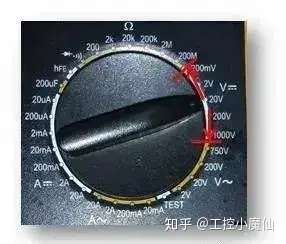
(3) Notes:
If you have no idea about the voltage range to be measured in advance, you should turn the range switch to the highest gear, and then turn it to the corresponding gear according to the displayed value;
When not measuring, there are residual numbers in the small voltage range, which is a normal phenomenon and does not affect the test; if the high position shows "1" during measurement, it means that the single-range range has been exceeded, and the range switch must be turned to a higher position;
The input voltage should not exceed 1000V. If it exceeds this limit, the instrument circuit may be damaged.
When measuring high voltage circuits, be careful to avoid touching the high voltage circuits.
AC voltage detection
(1) Insert the black test lead into the COM jack and the red test lead into the VΩ jack; (as shown in Figure 6)

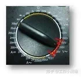
(2) Turn the range switch to the corresponding V~ range, and then connect the test leads across the test circuit. (As shown in Figure 7)
Precautions
(a) If you have no idea about the voltage range to be measured, you should turn the range switch to the highest position, and then turn it to the corresponding position according to the displayed value;
(b) When not measuring, there are residual numbers in the small voltage range, which is a normal phenomenon and does not affect the test; if the high position shows "1" during measurement, it means that the range has been exceeded and the range switch must be turned to a higher position;
(c) The input voltage must not exceed 700Vrms. If it exceeds this limit, there is a risk of damaging the instrument circuit.
(d) When measuring high voltage circuits, be careful to avoid touching the high voltage circuits.
DC current detection
(1) Insert the black test lead into the COM jack, the red test lead into the mA jack (maximum 2A), or the red test lead into the "20A" jack (maximum 20A); (as shown in Figure 8)
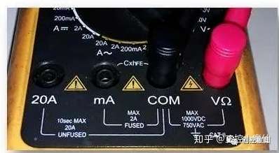
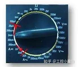
(2) Turn the range switch to the corresponding A position, and then connect the meter in series with the circuit to be measured. The measured current value and the current polarity of the red probe point will be displayed on the screen at the same time. (As shown in Figure 9)
Precautions
(a) If you have no idea about the current range to be measured, turn the range switch to the highest position, and then turn to the corresponding position according to the displayed value;
(b) If the LCD displays "1", it means that the range has been exceeded and the range switch must be adjusted up one level;
(c) The maximum input current is 2A or 20A (depending on the position of the red test lead). Excessive current will blow the fuse. When measuring at 20A, please note that this position has no protection. Continuous measurement of large current will cause the circuit to heat up, affecting the measurement accuracy and even damaging the instrument.
AC current detection
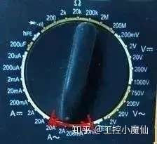
(1) Insert the black test lead into the "COM" jack, the red test lead into the "mA" jack (maximum 2A), or the red test lead into the "20A" jack (maximum 20A) (as shown in Figure 10);
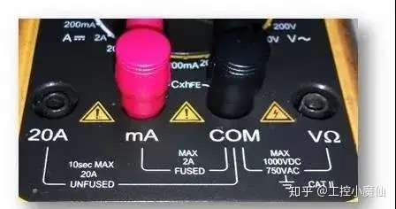
(2) Turn the range switch to the corresponding A~ position, and then connect the meter in series to the circuit to be measured. (As shown in Figure 11)
Precautions
(a) If you have no idea about the current range to be measured, turn the range switch to the highest position, and then turn to the corresponding position according to the displayed value;
(b) If the LCD displays "1", it means that the range has been exceeded and the range switch must be adjusted up one level;
(c) The maximum input current is 2A or 20A (depending on the position of the red test lead). Excessive current will blow the fuse. When measuring at 20A, please note that this position has no protection. Continuous measurement of large current will cause the circuit to heat up, affecting the measurement accuracy and even damaging the instrument.
Resistance Ω detection
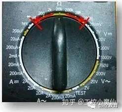
(1) Insert the black test lead into the "COM" jack and the red test lead into the "VΩ" jack; (as shown in Figure 12)

(2) Turn the range switch to the corresponding resistance range and connect the two test leads across the resistance to be measured. (As shown in Figure 13)
Precautions
(a) If the resistance value exceeds the selected range value, "1" will be displayed. At this time, the switch should be turned to a higher level. When the measured resistance value exceeds 1 MΩ, the reading will take several seconds to stabilize. This is normal when measuring high resistance.
(b) When the input terminal is open, it indicates an overload condition;
(c) When measuring online resistance, make sure that all power supplies of the circuit under test have been turned off and all capacitors have been fully discharged;
(d) Do not input voltage in the resistance range;
Diode/continuity detection
(1) Insert the black test lead into the "COM" jack and the red test lead into the "VΩ" jack; (as shown in Figure 14)

(2) Set the range switch to position (as shown in Figure 15) and connect the test leads to the diode to be tested, with the red test lead connected to the positive electrode of the diode. The reading is the approximate value of the forward voltage drop of the diode.

(3) Connect the test leads to two points of the circuit to be tested. If the built-in buzzer sounds, the resistance between the two points is less than approximately (70±20)Ω.
Capacitance C detection
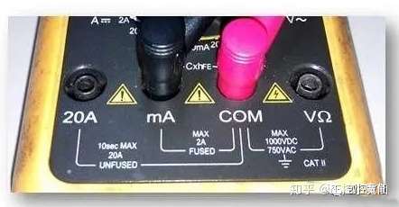
(1) Insert the red test lead into the "COM" jack and the black test lead into the "mA" jack; (as shown in Figure 16)
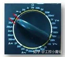
(2) Set the range switch to the capacitance range (as shown in Figure 17);
(3) Connect the test leads across the two ends of the capacitor for measurement. Pay attention to the polarity when measuring electrolytic capacitors and tantalum capacitors.
Precautions
(a) If the capacitance being measured exceeds the maximum value of the selected range, the display will only show 1. In this case, the switch should be turned up one gear.
(b) Before testing the capacitance, the display may still have residual readings, which is normal and does not affect the measurement results;
(c) Before testing large-capacity capacitors, please fully discharge the capacitors to prevent damage to the instrument.
FireWire Identification TEST
(1) Pull out the black test lead from the COM jack and leave only the red test lead inserted into the VΩ jack; (as shown in Figure 18)
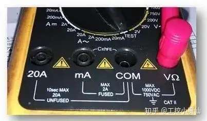
(2) Set the range switch to the TEST position and connect the red test lead to the circuit to be tested; (as shown in Figure 19)
(3) If the display shows 1 and there is sound and light
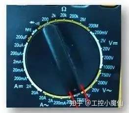
If an alarm sounds, the tested line connected to the red test lead is the live line. If there is no change, it is the neutral line.
Precautions
(a) This function only detects the standard AC live wire AC-110V~AC-380V;
(b) The first operation must be carried out under the instruction of the team leader;
Previous article:Detailed usage of digital multimeter
Next article:How to use a multimeter to distinguish between the neutral wire and the ground wire
- Popular Resources
- Popular amplifiers
-
 ICCV2023 Paper Summary: Deep Learning Architectures and Techniques
 -
 RBF neural network control design, analysis and Matlab simulation (Liu Jinkun)
 -
 Practical Development of Hongmeng HarmonyOS Mobile Applications (Liu Weiwei)
 -
 Chip Manufacturing: A Practical Tutorial on Semiconductor Process Technology (Sixth Edition)
- Keysight Technologies Helps Samsung Electronics Successfully Validate FiRa® 2.0 Safe Distance Measurement Test Case
- From probes to power supplies, Tektronix is leading the way in comprehensive innovation in power electronics testing
- Seizing the Opportunities in the Chinese Application Market: NI's Challenges and Answers
- Tektronix Launches Breakthrough Power Measurement Tools to Accelerate Innovation as Global Electrification Accelerates
- Not all oscilloscopes are created equal: Why ADCs and low noise floor matter
- Enable TekHSI high-speed interface function to accelerate the remote transmission of waveform data
- How to measure the quality of soft start thyristor
- How to use a multimeter to judge whether a soft starter is good or bad
- What are the advantages and disadvantages of non-contact temperature sensors?
- Innolux's intelligent steer-by-wire solution makes cars smarter and safer
- 8051 MCU - Parity Check
- How to efficiently balance the sensitivity of tactile sensing interfaces
- What should I do if the servo motor shakes? What causes the servo motor to shake quickly?
- 【Brushless Motor】Analysis of three-phase BLDC motor and sharing of two popular development boards
- Midea Industrial Technology's subsidiaries Clou Electronics and Hekang New Energy jointly appeared at the Munich Battery Energy Storage Exhibition and Solar Energy Exhibition
- Guoxin Sichen | Application of ferroelectric memory PB85RS2MC in power battery management, with a capacity of 2M
- Analysis of common faults of frequency converter
- In a head-on competition with Qualcomm, what kind of cockpit products has Intel come up with?
- Dalian Rongke's all-vanadium liquid flow battery energy storage equipment industrialization project has entered the sprint stage before production
- Allegro MicroSystems Introduces Advanced Magnetic and Inductive Position Sensing Solutions at Electronica 2024
- Car key in the left hand, liveness detection radar in the right hand, UWB is imperative for cars!
- After a decade of rapid development, domestic CIS has entered the market
- Aegis Dagger Battery + Thor EM-i Super Hybrid, Geely New Energy has thrown out two "king bombs"
- A brief discussion on functional safety - fault, error, and failure
- In the smart car 2.0 cycle, these core industry chains are facing major opportunities!
- The United States and Japan are developing new batteries. CATL faces challenges? How should China's new energy battery industry respond?
- Murata launches high-precision 6-axis inertial sensor for automobiles
- Ford patents pre-charge alarm to help save costs and respond to emergencies
- New real-time microcontroller system from Texas Instruments enables smarter processing in automotive and industrial applications
- Car central control 12V power supply filtering
- 【IoT Development】D3 engine has been upgraded! Come and experience the new version of Gizwits Intelligent Scene Push
- Serial port automatic transceiver chip
- Why does the amplitude of AD835 increase when the same frequency input is above 15M? How can I make the amplitude-frequency curve flatter?
- Today at 10:00 AM Award-winning live broadcast: Azure Sphere helps to provide stable, secure and flexible IoT solutions
- The role of capacitors
- I need help with a semiconductor-related book "Photolithography near the diffraction limit"
- New hot spot in automobiles: In-depth analysis of T-BOX system solutions
- What are the differences between 4G and 5G networks?
- Altera-FPGA programming steps and precautions

 ICCV2023 Paper Summary: Deep Learning Architectures and Techniques
 RBF neural network control design, analysis and Matlab simulation (Liu Jinkun)


 京公网安备 11010802033920号