Reluctance angle and linear position measurement systems are often used in motor control and are widely used. The following is a design solution for this measurement system, including hardware selection, software simulation and test results.
Circuit Function and Advantages
The compact two-chip circuit shown in Figure 1 provides a contactless anisotropic magnetoresistive (AMR) measurement solution for either angular or linear position measurement. The two-chip system has an angular accuracy of better than 0.2° over a 180° range and a linear accuracy of 2 mil (0.002 in.) over a 0.5 in. range, depending on the size of the magnet used.
The circuit is ideal for applications where high speed, high accuracy, non-contact angle and length measurement is critical, such as machine tool speed control, crane angle control, brushless DC motors, and other industrial or automotive applications.

Figure 1. Magnetoresistive angle and linear sensing system (Simplified schematic: decoupling and all connections not shown)
Circuit Description
The ADA4571 is an anisotropic magnetoresistive (AMR) sensor with integrated signal conditioning amplifiers and ADC drivers, as well as a temperature sensor for temperature compensation.
The ADA4571 generates two analog outputs that indicate the angular position of the surrounding magnetic field.
The ADA4571 integrates an AMR sensor and a fixed gain (nominal G = 40) instrumentation amplifier. The ADA4571 provides clean, amplified cosine and sine output signals related to the angle of the rotating magnetic field. The output voltage range is ratiometric to the supply voltage.
The sensor consists of two permalloy Wheatstone bridges at a 45° angle to each other. A rotating magnetic field in the xy sensor plane provides two sinusoidal output signals with double the frequency of the angle (α) between the sensor and the magnetic field direction. In a homogeneous field in the xy plane, the output signals are independent of the physical position in the z direction (air gap).
The output voltage swing on the sine and cosine outputs ranges from 7% VDD to 93% VDD. There are two diagnostic bands (0% to 7% of VDD and 93% to 100% of VDD), providing bond-break detection for all internal connections.
The ADA4571 is available in an 8-lead SOIC package.
The output impedance of the VSIN and VCOS outputs is 50Ω, forming a 318 kHz noise filter with external 10 nF capacitors.
The AD7866 is a dual-channel, simultaneous sampling, 12-bit, 1 MSPS SAR ADC. The polarity of the RANGE pin determines the analog input range and output code. If the pin is connected to a logic high when the chip select signal goes low, the analog input range for the next conversion is 0 V to 2 × VREF (0 V to 5 V), which provides approximately 350 mV of headroom for the 0.35 V to 4.65 V signal of the ADA4571 AMR sensor.
Connecting the REFSEL pin low configures the ADC to use the internal 2.5 V reference. This voltage is available at the VREF pin, but a buffer must be used before using it elsewhere in the system. Decoupling the DCAPA and DCAPB pins with 470 nF capacitors ensures proper ADC operation.
The AD7866 samples both channels of the sensor simultaneously. The digital words are normally available at DOUTA and DOUTB. Each data stream consists of a leading zero, followed by 3 status bits, followed by 12 bits of conversion data. However, by keeping the CS pin low for an additional 16 clock cycles, both digital words can be obtained from one channel (DOUTA). Therefore, the SPI interface allows access to both channels on one data line.
The AD7866 has two-channel multiplexers for both ADC inputs. A logic 0 on the A0 input pin allows the A1 and A2 inputs to switch, while a logic 1 on the A0 input pin allows the B1 and B2 inputs to switch. The temperature sensor output of the ADA4571 is connected to the B1 input of the AD7866 and allows software temperature calibration of the system.
Magnetoresistance (MR) theory
Magnetoresistance is the ability of a material to change its resistance value in the presence of an external magnetic field. The most commonly used MR sensors are based on AMR technology.
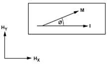
Figure 2. Anisotropic magnetoresistance example
An example of the AMR effect is shown in Figure 2. A current (I) flows through a conductor and is affected by an external magnetic field (HY). The change in resistance of the conductor is a function of the angle between the magnetization vector (M) and the current vector (I). The magnetization vector is the net sum of the internal magnetic field (HX) and the applied external magnetic field (HY).
When the magnetization vector (M) is parallel to the current vector (I), the resistance is maximum. When the magnetization vector (M) is perpendicular to the current vector (I), the resistance is minimum.
Effective use of the AMR effect requires that the conductor itself must be a material that is insensitive to mechanical stress but sensitive to magnetic confinement. For these reasons, permalloy (80% nickel, 20% iron) is the most commonly used alloy in the manufacture of AMR sensors.
Permalloy Properties
Permalloy strips have two properties that create design challenges when creating angle measurement systems.
First, permalloy has a narrow linear operating region (see Figure 3). The response is linear only when the angle between the magnetization vector (M) and the current vector (I) becomes larger. Unfortunately, the linear response is not long before permalloy saturates.
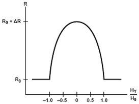
Figure 3. Relationship between permalloy resistance and magnetic field
Second, permalloy is insensitive to polarity. Whether the angle between the magnetization vector (M) and the current vector (I) is positive or negative, the resistance of a permalloy strip will drop.
Double color stripe magnetic pole
A common method to improve the linearity and pole insensitivity of permalloy strips is to add aluminum strips at 45° to the axial direction of the metal strip (called bicolor poles, as shown in Figure 4). Any current flowing between the bicolor poles will take the shortest path—the perpendicular path—and the angle between the current vector (I) and the magnetization vector (M) will be offset by 45°.
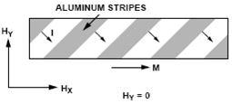
Figure 4. Double-color magnetic pole effect of permalloy strip
Figure 5 shows the result of adding a two-color stripe pole to the permalloy strip. The current vector is shifted by 45 degrees, but the magnetization vector remains the same. Note that the linear characteristic now exists in the center of the graph.
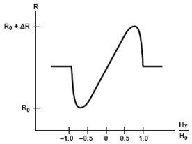
Figure 5. Relationship between resistance and magnetic field of double-color stripe magnetic pole permagnetic alloy
Magnetic field strength
A magnetic field strength of at least 25 kA/m is required to ensure that the specifications in the ADA4571 data sheet are met. This excitation magnetic field must intersect the center of the sensing element within the ADA4571 package.
When selecting a magnet, consider the air gap between the sensor and the magnet, as shown in Figure 6. If the magnet is not placed close to the sensor (that is, the distance d is very large), a stronger or larger magnet may be required to ensure that the minimum magnetic field strength requirement is met.
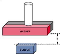
Figure 6. Magnet orientation and air gap for shaft angle measurement
Sensor Basics
A standard AMR sensor consists of two Wheatstone bridges placed at a 45° angle to each other, as shown in Figure 7.
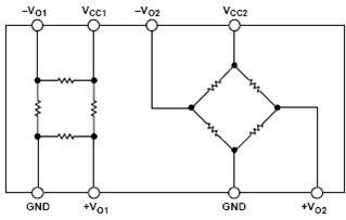
Figure 7. ADA4571 dual Wheatstone bridge configuration.
The rotating magnetic field produces sine and cosine output signals, as shown in Figure 8. Both signals are periodic over a 180° range, so full 360° measurement detection is not possible without additional components or reference points.
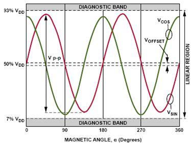
Figure 8. Magnetoresistive sensor output voltage
Channel sensitivity
The ADA4571 sensor has a nominal sensitivity of 52 mV/° per channel, which means that every degree change between the magnetization vector and the sensor orientation produces a 52 mV change in output voltage. The sensitivity of the angle is not a constant. The part of the output where the sensitivity decreases is where the slope of the line approaches zero.
As shown in Figure 8, the cosine output (green line) loses sensitivity when the magnetizing vector angle approaches 0°, 90°, 180°, or 270°. Similarly, the sine output (red line) loses sensitivity when the magnetizing vector angle approaches 45°, 135°, 225°, and 315°. Fortunately, when the sensitivity of one channel is reduced, the other channel is in a high sensitivity area.
System bandwidth, magnetic field rotation
The magnetic field angle vector is important to understand the bandwidth of the circuit. The ADC converts one sample every microsecond. To get 1° resolution, the magnetic field can only move 1° (2.778 kHz) in 1 ms, otherwise the ADC cannot sample fast enough to keep up with the speed of the magnetic field. For a 1 MSPS ADC, this means that the maximum available angular velocity of the magnetic field is 2.778 kHz.
Rotation measurement test results
A diametric N42 magnet (diameter = 0.5 in., thickness = 0.125 in.) is attached to the end of a metal rod. A precision DC motor provides fine angular control of the rod. The sensor is precisely mounted on the front face of the magnet. The air gap is set to 2 mm. The results are essentially independent of the air gap as long as the magnet excitation fully saturates the sensor.
The motor turns, creating a rotating magnetic field that intersects the sensor, which in turn produces repetitive sine and cosine output voltages suitable for angle calculation and data acquisition.
Figure 9 shows a functional block diagram of the setup. Figure 10 is a photograph of the setup, which can be used to acquire data in a shaft-end configuration. The setup consists of a BLDC motor, physical mounting, magnets, and a PCB with the corresponding ADA4571 sensor.
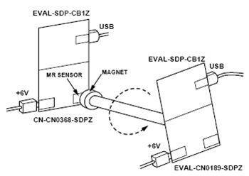
Figure 9. Data acquisition test setup - shaft tail configuration
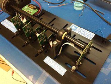
Figure 10. Photo of the BLDC motor benchmark test setup
Figure 11 compares the motor's mechanical angle to the sensor's calculated magnetic field angle over multiple revolutions of the magnet. The calculation uses the inverse tangent function of the ratio of the two outputs. Without calibration, the error is close to ±1°.
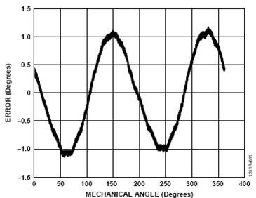
Figure 11. Angular error vs. mechanical angle before offset correction
Figure 12 shows the error with only one offset correction. No additional adjustments are required for amplitude mismatch, nonlinearity, or orthogonality correction of the sine and cosine. The offset value can be determined using the peak-to-peak or average value of each channel as it passes through the entire mechanical rotation. The offset is subtracted from the corresponding channel to obtain a linear sensor response. The maximum error is close to ±0.2°, while most of the error in the range is less than ±0.1°.
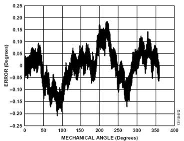
Figure 12. Angular error vs. mechanical angle after correction for offset only.
PCB Layout Considerations
The PCB of the CN-0368 system is a 4-layer stack-up with large ground and power layer polygons.
In any circuit where accuracy is important, careful consideration must be given to the layout of the power supply and ground return paths on the circuit board. The PCB should isolate the digital and analog sections as much as possible. See the MT-031 Tutorial for a detailed discussion of layout and grounding, and the MT-101 Tutorial for information on decoupling techniques.
The power supplies of all ICs should be decoupled with 1μF and 0.1μF capacitors to properly suppress noise and reduce ripple. These capacitors should be placed as close to the device as possible. Ceramic capacitors are recommended for all high-frequency decoupling.
The power trace should be as wide as possible to provide a low impedance path and reduce the glitch effect on the power line. The clock and other fast switching digital signals are shielded by digital ground so that they do not affect other devices on the board. Figure 13 is a photo of the PCB.
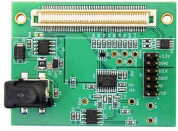
Figure 13. Photo of the EVAL-CN0368-SDPZ Board
Common changes
If sampling rates above 1 MSPS are required, the following simultaneous sampling ADCs should be considered;
If resolution greater than 12 or 14 bits is required, the AD7655 (16 bits at 1 MSPS) can be used.
Circuit Evaluation and Testing
This circuit uses the EVAL-SDP-CB1Z system demonstration platform (SDP) board and the EVAL-CN0368-SDPZ circuit board. The two boards have 120-pin mating connectors, allowing for quick setup and evaluation of the circuit performance.
The EVAL-SDP-CB1Z board is used with the CN0368 Evaluation Software to capture data from the EVAL-CN0368-SDPZ circuit board.
Equipment Requirements
The following equipment is needed:
PC with a USB port and Windows XP (32-bit), Windows Vista (32-bit), or Windows 7 (32-bit)
EVAL-CN0368-SDPZ circuit board
EVAL-SDP-CB1Z SDP板
6 V power supply or wall wart
CN0368 Evaluation Software
Neodymium magnet with magnetic field strength of not less than 25 kA/m at the sensor package
start using
Insert the CN0368 Evaluation Software CD into the PC and load the evaluation software. Open My Computer, locate the drive that contains the evaluation software CD, and open the Readme file. Follow the instructions in the Readme file to install and use the evaluation software.
Functional Block Diagram
Figure 14 shows a functional block diagram of the test setup.
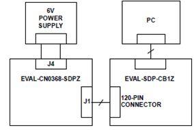
Figure 14. Test setup block diagram
set up
Connect the 120-pin connector on the EVAL-CN0368-SDPZ to the connector on the EVAL-SDP-CB1Z. Use nylon hardware to secure the two boards firmly, using the holes provided at the ends of the 120-pin connectors.
With power removed, connect the 6 V dc barrel jack to the J4 connector. Connect the USB cable provided with the EVAL-SDP-CB1Z to a USB port on the PC. Do not connect the USB cable to the micro-USB connector on the SDP board at this time.
Place the neodymium magnet directly on top of the IC or in a fixture designed for rotating magnets so that the distance between the IC and the magnet is minimized.
It is important to keep other sources of magnetic fields away from the IC because any stray magnetic field will produce errors in the sensor output voltage.
test
Apply power to the DC barrel jack, J4 connector. Launch the CN0368 evaluation software and connect the USB cable from the PC to the mini-USB connector on the EVAL-SDP-CB1Z.
Once USB communications are established, the EVAL-SDP-CB1Z can be used to send, receive, and capture serial data from the EVAL-CN0368-SDPZ.
Previous article:Synchronization Source: Clock in Power Measurement
Next article:How to use a multimeter to detect the quality of thermistors
- Popular Resources
- Popular amplifiers
- Keysight Technologies Helps Samsung Electronics Successfully Validate FiRa® 2.0 Safe Distance Measurement Test Case
- From probes to power supplies, Tektronix is leading the way in comprehensive innovation in power electronics testing
- Seizing the Opportunities in the Chinese Application Market: NI's Challenges and Answers
- Tektronix Launches Breakthrough Power Measurement Tools to Accelerate Innovation as Global Electrification Accelerates
- Not all oscilloscopes are created equal: Why ADCs and low noise floor matter
- Enable TekHSI high-speed interface function to accelerate the remote transmission of waveform data
- How to measure the quality of soft start thyristor
- How to use a multimeter to judge whether a soft starter is good or bad
- What are the advantages and disadvantages of non-contact temperature sensors?
- Innolux's intelligent steer-by-wire solution makes cars smarter and safer
- 8051 MCU - Parity Check
- How to efficiently balance the sensitivity of tactile sensing interfaces
- What should I do if the servo motor shakes? What causes the servo motor to shake quickly?
- 【Brushless Motor】Analysis of three-phase BLDC motor and sharing of two popular development boards
- Midea Industrial Technology's subsidiaries Clou Electronics and Hekang New Energy jointly appeared at the Munich Battery Energy Storage Exhibition and Solar Energy Exhibition
- Guoxin Sichen | Application of ferroelectric memory PB85RS2MC in power battery management, with a capacity of 2M
- Analysis of common faults of frequency converter
- In a head-on competition with Qualcomm, what kind of cockpit products has Intel come up with?
- Dalian Rongke's all-vanadium liquid flow battery energy storage equipment industrialization project has entered the sprint stage before production
- Allegro MicroSystems Introduces Advanced Magnetic and Inductive Position Sensing Solutions at Electronica 2024
- Car key in the left hand, liveness detection radar in the right hand, UWB is imperative for cars!
- After a decade of rapid development, domestic CIS has entered the market
- Aegis Dagger Battery + Thor EM-i Super Hybrid, Geely New Energy has thrown out two "king bombs"
- A brief discussion on functional safety - fault, error, and failure
- In the smart car 2.0 cycle, these core industry chains are facing major opportunities!
- The United States and Japan are developing new batteries. CATL faces challenges? How should China's new energy battery industry respond?
- Murata launches high-precision 6-axis inertial sensor for automobiles
- Ford patents pre-charge alarm to help save costs and respond to emergencies
- New real-time microcontroller system from Texas Instruments enables smarter processing in automotive and industrial applications
- Differences between CPU and CLA and Error Handling Techniques
- Automobile crankshaft dynamic balance problem-N600
- zstack protocol stack serial port problem
- MY-8188EUS Linux-3.14.52 Test
- MSP430 MCU Development Record (12)
- EEWORLD University Hall----Choosing the latest boost converter and Class D amplifier from Texas Instruments to significantly increase the battery life of the trolley speakers
- Award-winning live broadcast | TI Embedded Live Broadcast Month is waiting for you [Low-power Wi-Fi MCU, Sitara AM57X platform, machine learning]
- SPI settings for msp430f149
- Please recommend a board
- Streamlining mobile phone system design

 Evaluating Roadside Perception for Autonomous Vehicles: Insights from Field Testing
 ICCV2023 Paper Summary: Deep Learning Architectures and Techniques


 京公网安备 11010802033920号