1 Overall system design
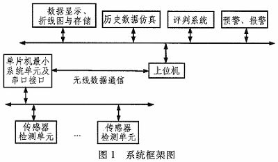
The corresponding detection device is installed on the part that needs to be measured. The detected analog voltage signal is converted into an amplified digital signal through the signal amplification and analog-to-digital conversion circuit. The wireless communication sending module receives and sends the processed data. The host computer part is equipped with a wireless communication receiving module, which receives data and sends it to the host computer through serial communication. The host computer performs calculations and judgments through the existing built-in algorithm and displays the results on the monitoring interface of the host computer. The overall design block diagram of the system is shown in Figure 1.
2 Hardware Structure
The hardware structure includes a sensor detection unit, a single-chip minimum system, a serial port interface, a power supply module, and a wireless communication module. The sensor detection unit includes a measuring element, a bridge circuit, a signal amplification circuit, an analog-to-digital conversion circuit, etc. The circuit diagram of the lower computer is shown in Figure 2.

Here, we take the measurement of stress value as an example. The sensor unit mainly includes resistance strain gauge, bridge circuit, power supply module, signal amplification circuit, analog-to-digital conversion circuit, etc. The external voltage of the bridge circuit is measured according to the measurement principle; the signal amplification circuit is used to amplify the received analog voltage of only millivolt level; due to the characteristics of analog signals that are difficult to transmit, process and easy to distort, the analog-to-digital conversion chip TLC1543 is used here to convert the analog signal into a digital signal; the single chip
The minimum system unit of the computer provides clock and reset functions for the circuit, and controls the conversion and transmission of signals; the high and low logic levels required for RS232 serial communication are 12 V and 0 V, which requires a level conversion circuit with MAX232 as the component, so that the host computer and the wireless receiving module can communicate.
3 Wireless Data Communication
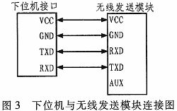
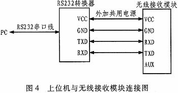
Wireless data communication is used to send the data collected by the lower computer to the upper computer, mainly including the sending of data from the lower computer and the receiving of data from the upper computer. The same baud rate, serial port check, etc. need to be set between the lower computer and the module, and the connection method is shown in Figure 3. The upper computer and the wireless receiving module are connected by an RS232 serial port line. Before that, an RS232 converter needs to be added to realize the interface conversion, and the connection method is shown in Figure 4.
4. Host computer software design
The realization of the host computer software mainly involves the design of built-in algorithms and interface design. The host computer receives and processes data, and displays the corresponding data on the monitoring interface, mainly including the display of stress data at each measurement point, the drawing of line graphs, data storage, and pre-alarm.
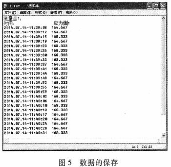
Here, we take the measurement of stress value as an example. Each sensor unit collects data that has been amplified and converted to analog. To obtain the data corresponding to each measurement point, it is necessary to process the received data and add an algorithm to obtain the measurement value of the measurement point. At this time, the read and write function of the edit box can be used to display the data in the edit box. The obtained stress data can be dynamically displayed in the view box containing the coordinate axis through the software implementation method. The stress change trend of the measurement point can be intuitively seen from the change of the curve. The obtained stress data can be saved in real time with time to a txt document through programming. The manager can process the data based on the saved data to restore the situation and change trend of the measurement point in the corresponding time period. The saved data is shown in Figure 5.
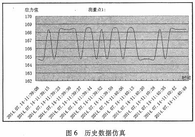
The manager can call up the saved data, select the data for the time period to be observed, and make a curve graph of the selected data through the data processing function of Excel. The mechanical deformation and change trend of the measured part in the time period can be observed. Figure 6 is a stress value change graph of a measuring point at a certain time period.
5 MFC monitoring interface and results
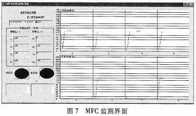
The system can save the processed data, correctly display the data and curve graphs, and when the measured value of a certain measuring point exceeds the corresponding specified value, it will make corresponding warnings and alarms.
Seeing the changes in the measured values at each measuring point has a good monitoring effect and a strong preventive function for accidents. Figure 7 is a monitoring interface obtained from an experimental measurement, where A and B are the corresponding warning values and alarm values, which depend on the actual measurement situation.
6 Conclusion
The circuit designed in this paper can collect the data measured by the sensor very well, and transmit it to the host computer through wireless transmission, solving the problem of multi-point data measurement and transmission. The designed sensor can measure the required measurement value very well and display it through the monitoring interface. The designed monitoring interface can display the relevant information very well.
Previous article:Design and implementation of a portable automatic test platform for shortwave receivers
Next article:How to perform CAN node signal characteristics test
- Keysight Technologies Helps Samsung Electronics Successfully Validate FiRa® 2.0 Safe Distance Measurement Test Case
- From probes to power supplies, Tektronix is leading the way in comprehensive innovation in power electronics testing
- Seizing the Opportunities in the Chinese Application Market: NI's Challenges and Answers
- Tektronix Launches Breakthrough Power Measurement Tools to Accelerate Innovation as Global Electrification Accelerates
- Not all oscilloscopes are created equal: Why ADCs and low noise floor matter
- Enable TekHSI high-speed interface function to accelerate the remote transmission of waveform data
- How to measure the quality of soft start thyristor
- How to use a multimeter to judge whether a soft starter is good or bad
- What are the advantages and disadvantages of non-contact temperature sensors?
- Innolux's intelligent steer-by-wire solution makes cars smarter and safer
- 8051 MCU - Parity Check
- How to efficiently balance the sensitivity of tactile sensing interfaces
- What should I do if the servo motor shakes? What causes the servo motor to shake quickly?
- 【Brushless Motor】Analysis of three-phase BLDC motor and sharing of two popular development boards
- Midea Industrial Technology's subsidiaries Clou Electronics and Hekang New Energy jointly appeared at the Munich Battery Energy Storage Exhibition and Solar Energy Exhibition
- Guoxin Sichen | Application of ferroelectric memory PB85RS2MC in power battery management, with a capacity of 2M
- Analysis of common faults of frequency converter
- In a head-on competition with Qualcomm, what kind of cockpit products has Intel come up with?
- Dalian Rongke's all-vanadium liquid flow battery energy storage equipment industrialization project has entered the sprint stage before production
- Allegro MicroSystems Introduces Advanced Magnetic and Inductive Position Sensing Solutions at Electronica 2024
- Car key in the left hand, liveness detection radar in the right hand, UWB is imperative for cars!
- After a decade of rapid development, domestic CIS has entered the market
- Aegis Dagger Battery + Thor EM-i Super Hybrid, Geely New Energy has thrown out two "king bombs"
- A brief discussion on functional safety - fault, error, and failure
- In the smart car 2.0 cycle, these core industry chains are facing major opportunities!
- The United States and Japan are developing new batteries. CATL faces challenges? How should China's new energy battery industry respond?
- Murata launches high-precision 6-axis inertial sensor for automobiles
- Ford patents pre-charge alarm to help save costs and respond to emergencies
- New real-time microcontroller system from Texas Instruments enables smarter processing in automotive and industrial applications
- [NXP Rapid IoT Review] NXP Rapid IOT Experience
- Is there any teacher who can help me write a program for Mitsubishi FX3U to output pulses?
- RTL8762, an excellent domestic BLE low-power solution
- Bear Pie Huawei IoT operating system LiteOS bare metal driver transplantation 01-Explain driver transplantation using LED as an example
- 【GD32450I-EVAL】Simple oscilloscope demonstration
- Shenzhen becomes the "world's first 5G city": challenges and business opportunities for the PCB industry
- 【Ended】 R&S Live 【PCI Express Gen 3 Conformance Test】
- Live broadcast at 10 am today [Renesas Electronics Secure IoT Suite provides you with secure cloud connection solutions
- Xun developed Qt for Android for i.MX6ULL Terminator QT application
- Applications of RF Transformers

 Mission-oriented wireless communications for cooperative sensing in intelligent unmanned systems


 京公网安备 11010802033920号