Introduction
Vehicle positioning and navigation technology is an important technology in intelligent transportation system (ITS), and positioning accuracy, continuity and reliability of positioning data are three important factors in navigation system performance. The accuracy of vehicle positioning and navigation depends directly on the accuracy of each sensor, and the improvement of sensor accuracy is often affected by factors such as technology and price. The currently widely used integrated navigation system based on multi-sensor fusion can effectively improve the navigation positioning accuracy, enhance the reliability of the navigation system, and fully guarantee the continuity and availability of navigation data. The number of sensors in the system is increasing, and traditional instruments no longer meet the system requirements. The author of this paper uses the multi-sensor information acquisition platform designed by NI's virtual instrument programming software LabVIEW to provide a general platform for multi-sensor information acquisition in integrated navigation, overcoming the shortcomings of traditional instruments with single functions, poor flexibility, and high update and maintenance costs. In addition, data acquisition, preprocessing, information display, storage and playback are integrated together to form a data file in a unified format, which is convenient for interfaces with other data analysis software, such as Matlab. In this multi-sensor information acquisition platform, various sensor information can be displayed on the same interface, and GPS time information can be easily added to the information of other sensors, solving the problem of difficulty in realizing multi-sensor information synchronization in the past.
Software Development Platform LabVIEW and Structure
LabVIEW stands for Laboratory Virtual Instrument Engineering Workbench. It is a very popular software development platform for virtual instruments. It is an integrated environment based on graphical development, debugging and running programs launched by National Instruments. It is the only compiled graphical programming language in the world.
System Hardware Structure
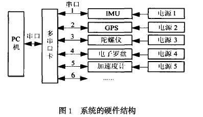
The hardware structure of this platform is shown in Figure 1. Various sensors are connected to the computer through a serial interface to achieve communication with the computer. The computer uses the system's LabVIEW program to send control commands to various sensors. Multi-sensor information is sent to the computer through the serial port for LabVIEW program to identify, read, store and post-process data. Various sensor information communicates with the computer through their respective interfaces in parallel. Due to limited laboratory conditions, the multi-sensor system design work was completed by taking IMU and GPS as examples.
System Software Structure
The software structure diagram of the system is shown in Figure 2. As can be seen from Figure 2, the entire system completes the functions of GPS/IMU data acquisition, data preprocessing, information display on the same interface, data storage, and data playback.

Key technologies of the system and their functional implementation
Key technologies of the system
(1) Parallel mechanism of LabVIEW
The LabVIEW software application uses a parallel program structure to realize the measurement and control of multi-sensor information. For example, in multi-task parallel processing, two loop structures constitute two parallel tasks. The execution order of each task body is independent of each other, and even the number of times the two tasks are executed can be different.
(2) Serial port communication subVI
The serial port communication subVI is for the computer standard serial port. LabVIEW provides a group (a total of 5) of serial port communication subVI controls to support programming, which are: ①Serial port initialization (Serial PortInit); ②Serial port read (Serial PortRead); ③Serial port write (Serial PortWrite); ④Serial port byte count (ByteSatSerialPort); ⑤Serial port interrupt (Serial PortBreak). (
3) Data synchronization mechanism principle
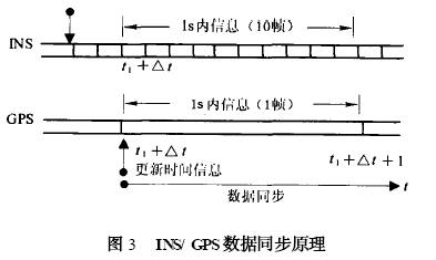
In multi-sensor information fusion, in order to minimize the error, the time of the two sensor data should match. However, in actual transmission of basic positioning information to the vehicle, only limited time information is needed. As long as the data start time is determined for the sensor information, the time can be determined based on the amount of data transmitted and the communication baud rate. Take the combination of GPS information and inertial navigation system (INS) as an example. Due to the different sampling rates of INS and GPS, the INS sampling rate is generally 10 Hz, while the GPS sampling rate is 1 Hz. As shown in Figure 3, let t1 be the time when IMU/INS and GPS information start to be available. First, a series of IMU/INS information is stored in the buffer from t1. Due to the low sampling rate of GPS, the GPS information at this time may not be the information at t1 but within the previous second. Assuming that the GPS information is updated at t1+Δt, after receiving the t1+Δt time information of GPS, the information in the buffer is restored to the correct time and the update is completed. Take t1+Δt as the data start time of the two sensors. In this way, the IMU/INS information and GPS information are time-matched. The subsequent time information can be determined by the amount of data transmitted and the communication baud rate.
System Function Implementation
(1) Data Collection and Preprocessing
After the sensor raw data is read correctly from the serial port continuously, the data is preprocessed. The raw data is converted into actual sensor measurement information through format conversion, mathematical calculation, etc., and the real-time measurement function of the IMU rotation angle is realized. The basic principle is to integrate the angular velocity over time to obtain the angle change value. Since the gyroscope has different degrees of zero drift at different temperatures, its error will continue to accumulate in the case of integration. Therefore, a subVI for real-time calculation of the average drift of each axis of the gyroscope when it is stationary is added to this module to compensate for the error of angular velocity integration, so as to obtain a more accurate angle change value. The following takes IMU as an example to illustrate the implementation process of converting raw data to actual measurement values. Each IMU information contains 18 bytes of information, and its definition is shown in Table 1. [page]
Table 1 IMU 18-byte positioning information
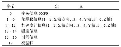
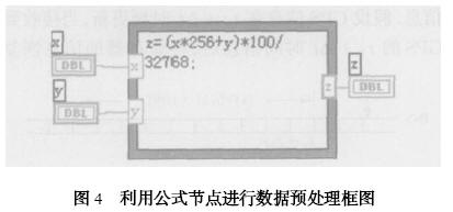
Figure 4 is a block diagram for data preprocessing using formula nodes. Among them, x and y are the input raw data, and z is the output actual measurement value. After the program converts the 18-byte string data into a digital array, the formula can be directly entered into the formula node on the block diagram to complete the conversion from the original information to the actual measured value.
(2) The information display
software uses a friendly and intuitive interface to present the information from the sensor, and presents the data information from the GPS and IMU respectively. Part of its interface is shown in Figure 5 and Figure 6.
During the design process, we specially used the Tab control, which can display the IMU and GPS information on different pages of the same panel at the same time, so that we can easily view the information of the two sensors interactively.
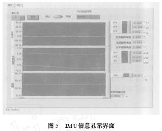
Figure 5 IMU information display interface
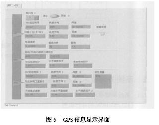
Figure 6 GPS information display interface
(3) Data storage
In LabVIEW, data can be stored in three formats: text file, binary file and data log file. The data storage function consists of a write file subVI and a Case structure. When the storage control button on the front panel is clicked, the system will store the IMU or GPS data, and the storage can be terminated at any time. Since there is no actual time information in the IMU information, in order to achieve the synchronization of multi-sensor information and the post-processing needs of the storage file, the synchronized GPS time information is added to the IMU storage information. In order to facilitate the use of other programs to read the data for post-processing, this paper adopts
the storage format of text files.
(3) Data playback
To play back the data, first identify the file according to its storage format, and then display the information on the interface. Since LabVIEW does not have many functions for reading files, and generally has strict requirements on file formats, we adopted a method that first reads all the strings in the file, and then uses the rich string operation functions in LabVIEW to separate, identify and process the read strings. The procedures for reading, processing, displaying, storing, and replaying GPS information are similar to those of IMU, except that they are slightly different in data format, which will not be described in this article.
Conclusion
A multi-sensor information acquisition platform was established using LabVIEW and existing laboratory equipment. This platform has good general performance and eliminates some tedious work in the operation process of multi-sensor information acquisition. The acquisition process no longer requires writing different software to adapt to different sensor requirements; multi-sensor information is displayed on the same interface, making the measurement information more intuitive; a unified format of data storage files is formed, which is conducive to the post-processing of multi-sensor storage information. This platform makes full use of the flexibility and multi-input and multi-output characteristics of virtual instruments, combines computers, multiple sensors, and LabVIEW software to form a virtual instrument system, realizes the measurement and control of multi-sensor information, and lays the foundation for further research on the use of virtual instruments to measure and control multi-sensor information and multi-sensor information fusion in the future.
Keywords:LabVIEW
Reference address:Multi-sensor information acquisition platform based on LabVIEW
Vehicle positioning and navigation technology is an important technology in intelligent transportation system (ITS), and positioning accuracy, continuity and reliability of positioning data are three important factors in navigation system performance. The accuracy of vehicle positioning and navigation depends directly on the accuracy of each sensor, and the improvement of sensor accuracy is often affected by factors such as technology and price. The currently widely used integrated navigation system based on multi-sensor fusion can effectively improve the navigation positioning accuracy, enhance the reliability of the navigation system, and fully guarantee the continuity and availability of navigation data. The number of sensors in the system is increasing, and traditional instruments no longer meet the system requirements. The author of this paper uses the multi-sensor information acquisition platform designed by NI's virtual instrument programming software LabVIEW to provide a general platform for multi-sensor information acquisition in integrated navigation, overcoming the shortcomings of traditional instruments with single functions, poor flexibility, and high update and maintenance costs. In addition, data acquisition, preprocessing, information display, storage and playback are integrated together to form a data file in a unified format, which is convenient for interfaces with other data analysis software, such as Matlab. In this multi-sensor information acquisition platform, various sensor information can be displayed on the same interface, and GPS time information can be easily added to the information of other sensors, solving the problem of difficulty in realizing multi-sensor information synchronization in the past.
Software Development Platform LabVIEW and Structure
LabVIEW stands for Laboratory Virtual Instrument Engineering Workbench. It is a very popular software development platform for virtual instruments. It is an integrated environment based on graphical development, debugging and running programs launched by National Instruments. It is the only compiled graphical programming language in the world.
System Hardware Structure
The hardware structure of this platform is shown in Figure 1. Various sensors are connected to the computer through a serial interface to achieve communication with the computer. The computer uses the system's LabVIEW program to send control commands to various sensors. Multi-sensor information is sent to the computer through the serial port for LabVIEW program to identify, read, store and post-process data. Various sensor information communicates with the computer through their respective interfaces in parallel. Due to limited laboratory conditions, the multi-sensor system design work was completed by taking IMU and GPS as examples.

System Software Structure
The software structure diagram of the system is shown in Figure 2. As can be seen from Figure 2, the entire system completes the functions of GPS/IMU data acquisition, data preprocessing, information display on the same interface, data storage, and data playback.

Key technologies of the system and their functional implementation
Key technologies of the system
(1) Parallel mechanism of LabVIEW
The LabVIEW software application uses a parallel program structure to realize the measurement and control of multi-sensor information. For example, in multi-task parallel processing, two loop structures constitute two parallel tasks. The execution order of each task body is independent of each other, and even the number of times the two tasks are executed can be different.
(2) Serial port communication subVI
The serial port communication subVI is for the computer standard serial port. LabVIEW provides a group (a total of 5) of serial port communication subVI controls to support programming, which are: ①Serial port initialization (Serial PortInit); ②Serial port read (Serial PortRead); ③Serial port write (Serial PortWrite); ④Serial port byte count (ByteSatSerialPort); ⑤Serial port interrupt (Serial PortBreak). (
3) Data synchronization mechanism principle
In multi-sensor information fusion, in order to minimize the error, the time of the two sensor data should match. However, in actual transmission of basic positioning information to the vehicle, only limited time information is needed. As long as the data start time is determined for the sensor information, the time can be determined based on the amount of data transmitted and the communication baud rate. Take the combination of GPS information and inertial navigation system (INS) as an example. Due to the different sampling rates of INS and GPS, the INS sampling rate is generally 10 Hz, while the GPS sampling rate is 1 Hz. As shown in Figure 3, let t1 be the time when IMU/INS and GPS information start to be available. First, a series of IMU/INS information is stored in the buffer from t1. Due to the low sampling rate of GPS, the GPS information at this time may not be the information at t1 but within the previous second. Assuming that the GPS information is updated at t1+Δt, after receiving the t1+Δt time information of GPS, the information in the buffer is restored to the correct time and the update is completed. Take t1+Δt as the data start time of the two sensors. In this way, the IMU/INS information and GPS information are time-matched. The subsequent time information can be determined by the amount of data transmitted and the communication baud rate.

System Function Implementation
(1) Data Collection and Preprocessing
After the sensor raw data is read correctly from the serial port continuously, the data is preprocessed. The raw data is converted into actual sensor measurement information through format conversion, mathematical calculation, etc., and the real-time measurement function of the IMU rotation angle is realized. The basic principle is to integrate the angular velocity over time to obtain the angle change value. Since the gyroscope has different degrees of zero drift at different temperatures, its error will continue to accumulate in the case of integration. Therefore, a subVI for real-time calculation of the average drift of each axis of the gyroscope when it is stationary is added to this module to compensate for the error of angular velocity integration, so as to obtain a more accurate angle change value. The following takes IMU as an example to illustrate the implementation process of converting raw data to actual measurement values. Each IMU information contains 18 bytes of information, and its definition is shown in Table 1. [page]
Table 1 IMU 18-byte positioning information

Figure 4 is a block diagram for data preprocessing using formula nodes. Among them, x and y are the input raw data, and z is the output actual measurement value. After the program converts the 18-byte string data into a digital array, the formula can be directly entered into the formula node on the block diagram to complete the conversion from the original information to the actual measured value.

(2) The information display
software uses a friendly and intuitive interface to present the information from the sensor, and presents the data information from the GPS and IMU respectively. Part of its interface is shown in Figure 5 and Figure 6.
During the design process, we specially used the Tab control, which can display the IMU and GPS information on different pages of the same panel at the same time, so that we can easily view the information of the two sensors interactively.

Figure 5 IMU information display interface

Figure 6 GPS information display interface
(3) Data storage
In LabVIEW, data can be stored in three formats: text file, binary file and data log file. The data storage function consists of a write file subVI and a Case structure. When the storage control button on the front panel is clicked, the system will store the IMU or GPS data, and the storage can be terminated at any time. Since there is no actual time information in the IMU information, in order to achieve the synchronization of multi-sensor information and the post-processing needs of the storage file, the synchronized GPS time information is added to the IMU storage information. In order to facilitate the use of other programs to read the data for post-processing, this paper adopts
the storage format of text files.
(3) Data playback
To play back the data, first identify the file according to its storage format, and then display the information on the interface. Since LabVIEW does not have many functions for reading files, and generally has strict requirements on file formats, we adopted a method that first reads all the strings in the file, and then uses the rich string operation functions in LabVIEW to separate, identify and process the read strings. The procedures for reading, processing, displaying, storing, and replaying GPS information are similar to those of IMU, except that they are slightly different in data format, which will not be described in this article.
Conclusion
A multi-sensor information acquisition platform was established using LabVIEW and existing laboratory equipment. This platform has good general performance and eliminates some tedious work in the operation process of multi-sensor information acquisition. The acquisition process no longer requires writing different software to adapt to different sensor requirements; multi-sensor information is displayed on the same interface, making the measurement information more intuitive; a unified format of data storage files is formed, which is conducive to the post-processing of multi-sensor storage information. This platform makes full use of the flexibility and multi-input and multi-output characteristics of virtual instruments, combines computers, multiple sensors, and LabVIEW software to form a virtual instrument system, realizes the measurement and control of multi-sensor information, and lays the foundation for further research on the use of virtual instruments to measure and control multi-sensor information and multi-sensor information fusion in the future.
Previous article:Temperature and humidity calibration system for environmental test equipment based on LabVIEW
Next article:Phase Demodulation Technology of Optical Fiber Sensor Based on Labview
Recommended ReadingLatest update time:2024-11-16 14:44
Several timers in labview

LABVIEW provides several timers (including DELAY), as shown in the figure below.
First, look at the help description of the Tick Count node:
Returns the value of the millisecond timer.
The base reference time (0 milliseconds) is undefined, that is, the returned milliseconds cannot be directly converted int
[Test Measurement]

Development of CAN bus communication platform based on LabVIEW and J1939 protocol

Overview: Since the beginning of the 21st century, the application of commercial vehicle CAN bus network has been developed extremely rapidly. Nowadays, commercial vehicles that meet the national 3 to national 5 emission standards on the market all use CAN bus network without exception to carry out data communicat
[Test Measurement]

LabVIEW Programming Style Guidelines II

The block diagram is the primary way that others understand how the VI works, so it is often helpful to follow some simple steps to make the block diagram more organized and easier to read. The style of the VI's block diagram is as important as the style of the front panel. The user may not see the block diagram, bu
[Test Measurement]

LabVIEW interface design - Modify the decoration color
Many people would go to great lengths to create a beautiful and exquisite interface, as can be seen from my colleague Chen Shuai. I personally believe that the interface is designed for the user, so simplicity is fine, just like a girl with a clean appearance is generally more attractive than a woman with heavy makeup.
[Test Measurement]
Labview Program Debugging Technology
Program debugging technology
Find grammatical errors
If a VI program has a syntax error, the Run button on the panel toolbar will become a broken arrow, indicating that the program cannot be executed. At this time, this button is called the Error List. Click it, and LabVIEW will pop up the Error List window. Clic
[Test Measurement]
B/S Mode Software Design of CNC Machine Tool Network Measurement and Control System Based on LabVIEW

Design of data acquisition, display, storage and playback software for lower-level measurement and control machines The lower-level measurement and control server system software includes two parts: interface instrument driver software and application software. Among them, the interface instrument driver is a collec
[Test Measurement]

Labview programming skills---fixed-point conversion

A string of PCM data is received, as follows:
0000 1264 C97C 8937 77C8 3783 EE9B 0000
indicates that two bytes correspond to one point of data (after the high and low bits are swapped, such as: 1264 (as it is stored), the actual value is: 6412 (hexadecimal), and their corresponding decimal floating-point numbers
[Test Measurement]

PCB test system design
Combine NI PXI and PCI hardware with NI TestStand and LabVIEW software to develop a standard test system for testing printed circuit boards and solar inverters.
"Using development tools exclusively from National Instruments, we developed a complete solution that covers all test needs from printed circuit board
[Test Measurement]
- Popular Resources
- Popular amplifiers
-
 100 Examples of Microcontroller C Language Applications (with CD-ROM, 3rd Edition) (Wang Huiliang, Wang Dongfeng, Dong Guanqiang)
 -
 Arduino Nano collects temperature and humidity data through LabVIEW and DHT11
 -
 Multi-Sensor Data Fusion: An Introduction
 -
 Modern Testing Technology and System Integration (Liu Junhua)
Recommended Content
Latest Test Measurement Articles
- Keysight Technologies Helps Samsung Electronics Successfully Validate FiRa® 2.0 Safe Distance Measurement Test Case
- From probes to power supplies, Tektronix is leading the way in comprehensive innovation in power electronics testing
- Seizing the Opportunities in the Chinese Application Market: NI's Challenges and Answers
- Tektronix Launches Breakthrough Power Measurement Tools to Accelerate Innovation as Global Electrification Accelerates
- Not all oscilloscopes are created equal: Why ADCs and low noise floor matter
- Enable TekHSI high-speed interface function to accelerate the remote transmission of waveform data
- How to measure the quality of soft start thyristor
- How to use a multimeter to judge whether a soft starter is good or bad
- What are the advantages and disadvantages of non-contact temperature sensors?
MoreSelected Circuit Diagrams
MorePopular Articles
- Innolux's intelligent steer-by-wire solution makes cars smarter and safer
- 8051 MCU - Parity Check
- How to efficiently balance the sensitivity of tactile sensing interfaces
- What should I do if the servo motor shakes? What causes the servo motor to shake quickly?
- 【Brushless Motor】Analysis of three-phase BLDC motor and sharing of two popular development boards
- Midea Industrial Technology's subsidiaries Clou Electronics and Hekang New Energy jointly appeared at the Munich Battery Energy Storage Exhibition and Solar Energy Exhibition
- Guoxin Sichen | Application of ferroelectric memory PB85RS2MC in power battery management, with a capacity of 2M
- Analysis of common faults of frequency converter
- In a head-on competition with Qualcomm, what kind of cockpit products has Intel come up with?
- Dalian Rongke's all-vanadium liquid flow battery energy storage equipment industrialization project has entered the sprint stage before production
MoreDaily News
- Allegro MicroSystems Introduces Advanced Magnetic and Inductive Position Sensing Solutions at Electronica 2024
- Car key in the left hand, liveness detection radar in the right hand, UWB is imperative for cars!
- After a decade of rapid development, domestic CIS has entered the market
- Aegis Dagger Battery + Thor EM-i Super Hybrid, Geely New Energy has thrown out two "king bombs"
- A brief discussion on functional safety - fault, error, and failure
- In the smart car 2.0 cycle, these core industry chains are facing major opportunities!
- The United States and Japan are developing new batteries. CATL faces challenges? How should China's new energy battery industry respond?
- Murata launches high-precision 6-axis inertial sensor for automobiles
- Ford patents pre-charge alarm to help save costs and respond to emergencies
- New real-time microcontroller system from Texas Instruments enables smarter processing in automotive and industrial applications
Guess you like
- MSP430FR series unused pin processing
- Why do different simulation results appear when the parameters of this simulation routine are set the same?
- Keil strange compilation problem
- EEWORLD University Hall----Live Replay: TI's Latest Application of Millimeter-Wave Radar in the Automotive Field
- Design of temperature measurement system based on msp430 single chip microcomputer
- Single power supply single op amp second order filter plus DC bias (cannot be isolated)
- Book now to get a gift: 2019 Keysight Electronic Measurement Basics Online Lecture Series
- Thank you + my parents
- Useful Information | A technical expert shares 15 tips on power MOSFET [Collect it]
- New Industry, New Smart Manufacturing——STMicroelectronics Industrial Tour 2019 Chengdu invites you to participate!

 100 Examples of Microcontroller C Language Applications (with CD-ROM, 3rd Edition) (Wang Huiliang, Wang Dongfeng, Dong Guanqiang)
 Arduino Nano collects temperature and humidity data through LabVIEW and DHT11


 京公网安备 11010802033920号