This article introduces a custom second-order PLL and shows how it can be properly applied to serial data measurements to improve eye diagram and jitter measurement accuracy.
Jitter is defined as the timing uncertainty of an edge. To determine the timing uncertainty of a serial data signal edge, the edge needs to be compared with a reference clock edge.
For most high-speed serial data standards, the reference clock is embedded in the serial data signal and needs to be recovered from the measured signal during testing. The method of recovering the clock will directly affect the shape of the measured eye diagram and the magnitude of the jitter value.
Some current serial data standards define not only standard methods for measuring jitter, but also standard methods for clock recovery.
Changes in low-frequency signal edges can be tracked by the PLL, but are not reflected in the measured jitter because they are effectively removed by the PLL. Conversely, changes in low-frequency signal edges that are not removed by the PLL will be measured as jitter. Therefore, the choice of clock recovery method affects both the tracking capability of the PLL and the final measured jitter value.
Flexible clock recovery in jitter measurement systems not only helps support the measurement needs defined by regulatory standards, but also serves as a powerful analysis tool that allows you to predict real receiver performance.
How PLLs adapt to signal changes
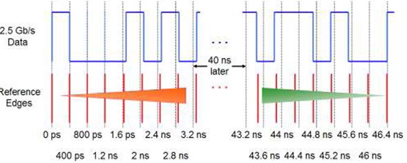
To compensate for slow timing changes in the serial data stream, the software clock recovery method can generate a reference edge position, and it will slowly adjust accordingly according to the low-frequency waveform drift, and high-speed jitter can be measured at the same time. As shown in Figure 1, with a defined cutoff frequency, the slow changes in the signal rate are tracked according to the increase or decrease in the rate of change of the reference edge timing. The edge timing frequency components below the software PLL bandwidth are tracked, and the high-frequency jitter part passes through the software filter to measure the high-frequency jitter value.

Figure 1. Tracking slowly changing signals by referring to slowly changing edges.
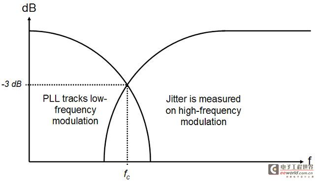
Figure 2 below shows a single-pole PLL that tracks low-frequency modulation, while high-frequency modulation is not tracked and is measured as jitter. The roll-off curve of a single-pole low-pass filter is a gradual process, resulting in a relatively large frequency range in the crossover region, which is both tracked and measured as jitter.

Figure 2 Single-pole PLL and JTF
Applications of Second-Order PLL
Correspondingly, the slow roll-off rate of the single-pole PLL brings about the limitation of the jitter transfer function (JTF). In order to ensure that high-frequency jitter is cut off at the low-frequency end and pass the jitter transfer function JTF to the greatest extent, a higher-order PLL is required.
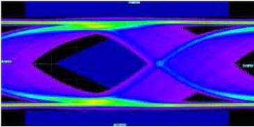
In some high-speed serial data standards, such as PCI Express, Serial SATA and SAS, spread spectrum clock (SSC) technology is needed to reduce EMI emission interference. The frequency of SSC modulation is in the low frequency range, about 30-33KHz. Figure 3 shows the eye diagram measured without a second-order PLL when SSC is present. After the eye diagram waveform is modulated by SSC, the basic jitter and eye diagram measurements are incorrect. Using a second-order PLL, as shown in Figure 4, the user can enter the natural frequency and damping coefficient to reduce the size of the crossover area and prevent attenuation within the band to the greatest extent.

Figure 3 Eye diagram measured with a first-order PLL with SSC

Figure 4 Custom second-order PLL setup interface

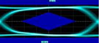
Figure 5: Eye diagram with SSS and measured using a second-order PLL
Figure 5 shows the same signal but with a second-order PLL, with the natural frequency set to 1MHz and the damping factor set to 0.707. The second-order PLL allows for a faster low-frequency cutoff and a better transfer function, capable of tracking linear phase and frequency variations within the PLL bandwidth.
Conclusion
The reference clock recovery function is an essential part of jitter measurement, and the characteristics of this function affect the tracking capability and the magnitude of the measured jitter value. The tracking capability of the PLL is important for accurate eye diagram and jitter measurements with SSC, and the high-pass cutoff frequency of the jitter transfer function controls the measured jitter value. In this respect, the jitter measurement system can be used to simulate the operation of a serial data receiver, so that the performance of a real receiver can be accurately predicted and evaluated.
Previous article:Oscilloscope Probe Basics Series 5 - Oscilloscope Probe Usage Guide (Part 1)
Next article:Measurement data rounding algorithm
- Keysight Technologies Helps Samsung Electronics Successfully Validate FiRa® 2.0 Safe Distance Measurement Test Case
- From probes to power supplies, Tektronix is leading the way in comprehensive innovation in power electronics testing
- Seizing the Opportunities in the Chinese Application Market: NI's Challenges and Answers
- Tektronix Launches Breakthrough Power Measurement Tools to Accelerate Innovation as Global Electrification Accelerates
- Not all oscilloscopes are created equal: Why ADCs and low noise floor matter
- Enable TekHSI high-speed interface function to accelerate the remote transmission of waveform data
- How to measure the quality of soft start thyristor
- How to use a multimeter to judge whether a soft starter is good or bad
- What are the advantages and disadvantages of non-contact temperature sensors?
- Innolux's intelligent steer-by-wire solution makes cars smarter and safer
- 8051 MCU - Parity Check
- How to efficiently balance the sensitivity of tactile sensing interfaces
- What should I do if the servo motor shakes? What causes the servo motor to shake quickly?
- 【Brushless Motor】Analysis of three-phase BLDC motor and sharing of two popular development boards
- Midea Industrial Technology's subsidiaries Clou Electronics and Hekang New Energy jointly appeared at the Munich Battery Energy Storage Exhibition and Solar Energy Exhibition
- Guoxin Sichen | Application of ferroelectric memory PB85RS2MC in power battery management, with a capacity of 2M
- Analysis of common faults of frequency converter
- In a head-on competition with Qualcomm, what kind of cockpit products has Intel come up with?
- Dalian Rongke's all-vanadium liquid flow battery energy storage equipment industrialization project has entered the sprint stage before production
- Allegro MicroSystems Introduces Advanced Magnetic and Inductive Position Sensing Solutions at Electronica 2024
- Car key in the left hand, liveness detection radar in the right hand, UWB is imperative for cars!
- After a decade of rapid development, domestic CIS has entered the market
- Aegis Dagger Battery + Thor EM-i Super Hybrid, Geely New Energy has thrown out two "king bombs"
- A brief discussion on functional safety - fault, error, and failure
- In the smart car 2.0 cycle, these core industry chains are facing major opportunities!
- The United States and Japan are developing new batteries. CATL faces challenges? How should China's new energy battery industry respond?
- Murata launches high-precision 6-axis inertial sensor for automobiles
- Ford patents pre-charge alarm to help save costs and respond to emergencies
- New real-time microcontroller system from Texas Instruments enables smarter processing in automotive and industrial applications
- Improved logging
- [Image recognition classification & motion detection & analog signal processing system based on Raspberry Pi 400, fifth post] Project conclusion & documentation - 11.0...
- EEWORLD University Hall----Live Replay: ADI - Inertial MEMS Applications
- Using FreeRTOS notification functions to speed up application execution
- 【AT-START-F425 Review】First Look at AT32F425
- Circuit analysis, please help me
- Personal income tax
- Interpretation for you | Introduction to the second version of 5G standard specification R16
- bq4050 protection recovery problem
- Reflections and how to handle them in high-speed systems

 Signal Integrity and Power Integrity Analysis (Eric Bogatin)
 HSPICE, Signal Integrity


 京公网安备 11010802033920号