1. Introduction
The Next Generation Network (NGN) is the era of optical networks. Telephone/TV/Internet in the home will be realized through an optical fiber. Therefore, the stability of this optical fiber is particularly important.
According to the statistics of the optical fiber network failure rate of Japan's NTT, the failure rate of optical fiber network is twice that of metal network. According to statistical analysis, the failure rate of China's FTTx optical fiber network will reach 140 cases/month per 10,000 users. That is to say, if the number of FTTx users in a city reaches 1 million, 14,000 failures will occur every month. With such a high number of failures, we still need to maintain a relatively high network reliability. When a failure occurs, we must be able to quickly troubleshoot and restore the optical fiber line. It is difficult to achieve effective optical fiber network management and maintenance by manpower alone. This requires us to establish an effective optical network centralized measurement system (RFTS). The RFTS system
is placed at the optical cable end office, and the OTDR board components dedicated to the xPON line are used to measure the core wires (currently used/idle) in the optical cable in turn, and regular monitoring and maintenance can be carried out. Its advantages are as follows:
● Greatly improve the efficiency of optical line maintenance and operation management. It can mainly conduct real-time online physical link monitoring and achieve early warning and forecasting. Automatically report specific information of the fault point and can effectively locate it. Regularly conduct quality statistical analysis to focus on maintaining weak points.
● When detecting faults such as increased loss, broken wires, and water in the joint box, the monitoring terminal will prompt different sound and light alarms according to the alarm level.
● While displaying the location of the fault on the electronic map, it will also notify the maintenance person in charge by email or phone. The fault location can be quickly determined to improve the efficiency of recovery operations.
● When conducting optical cable projects, the construction situation can be tested from the center through remote manual testing. Multiple cores can be concentrated for automatic testing. It can greatly reduce maintenance costs, reduce the on-site workload and number of visits of operation and maintenance personnel, reduce the number of instruments equipped by each operation and maintenance unit, effectively speed up troubleshooting, shorten the duration of faults, and improve operation quality.
● Regular automatic testing can be used to warn and forecast optical lines and greatly enhance the efficiency of optical cable maintenance and management.
2. Overview of the centralized optical measurement system RFTS
The composition of the RFTS system is shown in the figure below.
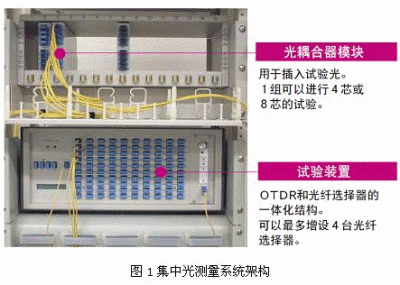
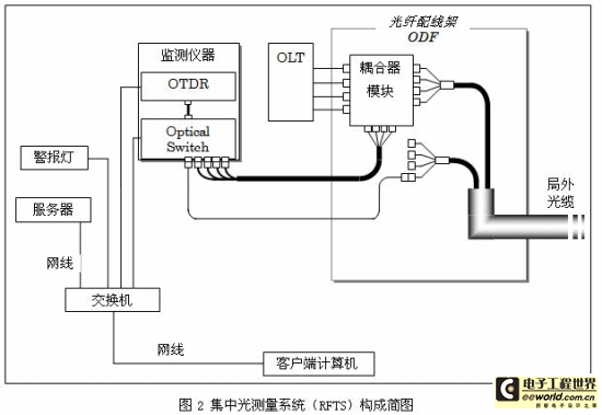
RFTS monitoring instruments, servers, alarm lights, and client computers are interconnected through network cables, so that remote control can be achieved. In a central computer room, through the connection of a general network, the monitoring instruments in the remote central office can be controlled to test the optical fiber network.
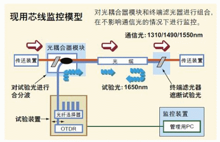
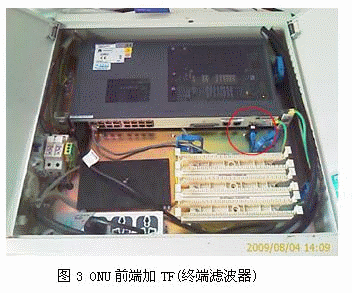
The RFTS system can monitor the spare optical fiber and also realize online monitoring. Through the "coupler module (Test Access Module-TAM)" configured on the optical fiber distribution frame, the communication signal light (OLT signal) and the test signal light (1.65um light) can be combined and then input into the external optical cable together. Before the ONU at the user end, a termination filter (Termination Filter-TF) needs to be added to filter out the test signal light to prevent it from affecting the ONU.
3. Functions of the centralized optical measurement system RFTS
3.1 Fiber optic network construction period
In the past fiber optic network construction period, when a project was completed, professional technicians were required to take a portable OTDR to the site for testing. With the RFTS system, the quality of the external optical fiber network can be tested in the central computer room without having to go to the site. At the same time, the RFTS system can perform quality inspections on the entire link of the optical fiber network. RFTS makes completion acceptance simpler and more convenient.
3.2 Fiber optic network operation and maintenance period
The current fiber optic network maintenance is generally handled after user complaints occur. Moreover, technicians take various instruments such as OTDR to the site to investigate the type and cause of the fault. This type of maintenance is both time-consuming and labor-intensive. The
RFTS system can perform regular inspections on external optical fiber lines, or it can perform continuous inspections. It can detect the occurrence of faults in a timely manner and analyze the types of faults. When a fault occurs, the RFTS system can issue an alarm or notify the relevant person in charge or maintenance personnel of the fault information through email or SMS. This allows line maintenance personnel to carry out maintenance in a timely manner and can bring necessary tools to the site in a targeted manner. The time required for fiber optic line maintenance is greatly reduced.
When a fault occurs in the optical cable trunk line, if there is a relevant electronic map to cooperate, RFTS can also indicate the location of the fault on the map. This allows maintenance personnel to rush to the fault location in a timely manner and improve the recovery speed of the optical cable line.
The RFTS system also has a manual test function. When a user complains, we can conduct a manual test to check the specific optical fiber line. It can effectively distinguish whether the fault is caused by the optical line or the ONU or other equipment in the user's home. This can avoid unnecessary dispatch of line maintenance personnel.
3.3 Management of FTTx users
In the current optical fiber network, each FTTx user has not been effectively managed. The RFTS system can assign a high reflection peak to each FTTH user through the filter set at the front end of the ONU, as shown in the figure below. When a normal peak appears, it proves that the user's line is normal. When a peak disappears or becomes very low, it proves that there is a problem with the user's line. Information such as the distance from this user to the central office can be managed in the RFTS system.
3.4 Other functions
The RFTS system can detect the length of the optical fiber line. It can display the optical loss within a section of the optical fiber line, and it can also display the optical loss between two points.
The RFTS system can save the test data in the database. When necessary, it can be searched and called out in various ways.
The RFTS system can print the test results, or it can be output or printed after forming a report. The detected raw data can also be output in the form of csv files. It is convenient for data editing and data preservation.
The RFTS system can be connected to various systems such as the PON port management system to achieve more effective and complete optical network management. [page]
4. Nanjing Putian RFTS case application
This is the detection result of the EPON optical fiber line after the application of RFTS in a certain community.
The main part of the optical fiber can be located to the point to ensure timely and accurate repair of obstacles; the reflection of each line can also be seen at the back end of the splitter.
Figure 4 shows that the optical splitter is about 1.7km away. The waveform before the optical splitter is smooth and complete, indicating that the quality of the trunk optical fiber line is good. The 8 peaks after the optical splitter represent 8 ONU terminals.
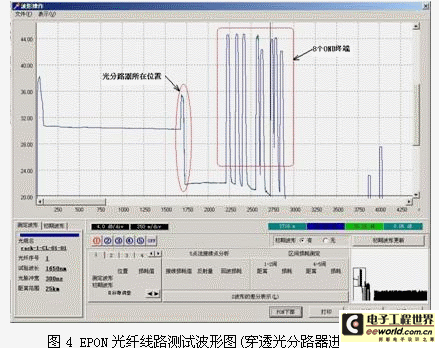
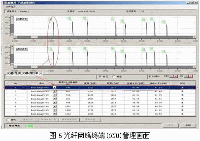
Figure 5 is a waveform diagram of the lower part of PON, and the 8 peaks in the figure represent 8 ONU user terminals. For example, the first peak represents the corridor box set up in the second unit of Building 33 in a certain community, and the distance from the local end is 2212 meters. The second peak represents the corridor box set up in the second unit of Building 30. By analogy, the specific locations of all terminal ONU corridor cabinets and the measurement of optical fiber loss can be defined.
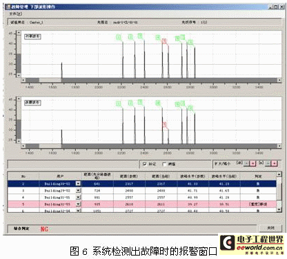
From the system notification shown in Figure 6, it is the optical fiber in the corridor box of Unit 3, Building 31 that has an alarm. This means that the terminal filter of this unit has been tampered with, or the optical fiber line from the optical splitter to the ONU of this unit is broken, and the line before the splitter is intact. The system is set to test regularly (once every 6 hours), and the fault was detected at around 12:03 noon on August 21. The system was restored through the troubleshooting. The entire system test was accurate and effective.
5. Conclusion
The construction and application of high-quality NGN requires a new system for optical fiber network troubleshooting/optical fiber network management and maintenance, and this system is RFTS.
Through RFTS, we can more efficiently check the quality of the external optical fiber network at the local end without going out;
through regular or continuous testing of RFTS, we can promptly discover the occurrence of faults;
the various fault information provided by RFTS can help us repair the optical fiber network more quickly;
RFTS can store various optical fiber network test data, and it is convenient to call out and view, so as to achieve effective comprehensive management.
Keywords:FTTx
Reference address:FTTx Centralized Optical Measurement System
The Next Generation Network (NGN) is the era of optical networks. Telephone/TV/Internet in the home will be realized through an optical fiber. Therefore, the stability of this optical fiber is particularly important.
According to the statistics of the optical fiber network failure rate of Japan's NTT, the failure rate of optical fiber network is twice that of metal network. According to statistical analysis, the failure rate of China's FTTx optical fiber network will reach 140 cases/month per 10,000 users. That is to say, if the number of FTTx users in a city reaches 1 million, 14,000 failures will occur every month. With such a high number of failures, we still need to maintain a relatively high network reliability. When a failure occurs, we must be able to quickly troubleshoot and restore the optical fiber line. It is difficult to achieve effective optical fiber network management and maintenance by manpower alone. This requires us to establish an effective optical network centralized measurement system (RFTS). The RFTS system
is placed at the optical cable end office, and the OTDR board components dedicated to the xPON line are used to measure the core wires (currently used/idle) in the optical cable in turn, and regular monitoring and maintenance can be carried out. Its advantages are as follows:
● Greatly improve the efficiency of optical line maintenance and operation management. It can mainly conduct real-time online physical link monitoring and achieve early warning and forecasting. Automatically report specific information of the fault point and can effectively locate it. Regularly conduct quality statistical analysis to focus on maintaining weak points.
● When detecting faults such as increased loss, broken wires, and water in the joint box, the monitoring terminal will prompt different sound and light alarms according to the alarm level.
● While displaying the location of the fault on the electronic map, it will also notify the maintenance person in charge by email or phone. The fault location can be quickly determined to improve the efficiency of recovery operations.
● When conducting optical cable projects, the construction situation can be tested from the center through remote manual testing. Multiple cores can be concentrated for automatic testing. It can greatly reduce maintenance costs, reduce the on-site workload and number of visits of operation and maintenance personnel, reduce the number of instruments equipped by each operation and maintenance unit, effectively speed up troubleshooting, shorten the duration of faults, and improve operation quality.
● Regular automatic testing can be used to warn and forecast optical lines and greatly enhance the efficiency of optical cable maintenance and management.
2. Overview of the centralized optical measurement system RFTS
The composition of the RFTS system is shown in the figure below.


RFTS monitoring instruments, servers, alarm lights, and client computers are interconnected through network cables, so that remote control can be achieved. In a central computer room, through the connection of a general network, the monitoring instruments in the remote central office can be controlled to test the optical fiber network.
The RFTS system can monitor the spare optical fiber and also realize online monitoring. Through the "coupler module (Test Access Module-TAM)" configured on the optical fiber distribution frame, the communication signal light (OLT signal) and the test signal light (1.65um light) can be combined and then input into the external optical cable together. Before the ONU at the user end, a termination filter (Termination Filter-TF) needs to be added to filter out the test signal light to prevent it from affecting the ONU.

3. Functions of the centralized optical measurement system RFTS
3.1 Fiber optic network construction period
In the past fiber optic network construction period, when a project was completed, professional technicians were required to take a portable OTDR to the site for testing. With the RFTS system, the quality of the external optical fiber network can be tested in the central computer room without having to go to the site. At the same time, the RFTS system can perform quality inspections on the entire link of the optical fiber network. RFTS makes completion acceptance simpler and more convenient.
3.2 Fiber optic network operation and maintenance period
The current fiber optic network maintenance is generally handled after user complaints occur. Moreover, technicians take various instruments such as OTDR to the site to investigate the type and cause of the fault. This type of maintenance is both time-consuming and labor-intensive. The
RFTS system can perform regular inspections on external optical fiber lines, or it can perform continuous inspections. It can detect the occurrence of faults in a timely manner and analyze the types of faults. When a fault occurs, the RFTS system can issue an alarm or notify the relevant person in charge or maintenance personnel of the fault information through email or SMS. This allows line maintenance personnel to carry out maintenance in a timely manner and can bring necessary tools to the site in a targeted manner. The time required for fiber optic line maintenance is greatly reduced.
When a fault occurs in the optical cable trunk line, if there is a relevant electronic map to cooperate, RFTS can also indicate the location of the fault on the map. This allows maintenance personnel to rush to the fault location in a timely manner and improve the recovery speed of the optical cable line.
The RFTS system also has a manual test function. When a user complains, we can conduct a manual test to check the specific optical fiber line. It can effectively distinguish whether the fault is caused by the optical line or the ONU or other equipment in the user's home. This can avoid unnecessary dispatch of line maintenance personnel.
3.3 Management of FTTx users
In the current optical fiber network, each FTTx user has not been effectively managed. The RFTS system can assign a high reflection peak to each FTTH user through the filter set at the front end of the ONU, as shown in the figure below. When a normal peak appears, it proves that the user's line is normal. When a peak disappears or becomes very low, it proves that there is a problem with the user's line. Information such as the distance from this user to the central office can be managed in the RFTS system.

3.4 Other functions
The RFTS system can detect the length of the optical fiber line. It can display the optical loss within a section of the optical fiber line, and it can also display the optical loss between two points.
The RFTS system can save the test data in the database. When necessary, it can be searched and called out in various ways.
The RFTS system can print the test results, or it can be output or printed after forming a report. The detected raw data can also be output in the form of csv files. It is convenient for data editing and data preservation.
The RFTS system can be connected to various systems such as the PON port management system to achieve more effective and complete optical network management. [page]
4. Nanjing Putian RFTS case application
This is the detection result of the EPON optical fiber line after the application of RFTS in a certain community.
The main part of the optical fiber can be located to the point to ensure timely and accurate repair of obstacles; the reflection of each line can also be seen at the back end of the splitter.
Figure 4 shows that the optical splitter is about 1.7km away. The waveform before the optical splitter is smooth and complete, indicating that the quality of the trunk optical fiber line is good. The 8 peaks after the optical splitter represent 8 ONU terminals.

Figure 5 is a waveform diagram of the lower part of PON, and the 8 peaks in the figure represent 8 ONU user terminals. For example, the first peak represents the corridor box set up in the second unit of Building 33 in a certain community, and the distance from the local end is 2212 meters. The second peak represents the corridor box set up in the second unit of Building 30. By analogy, the specific locations of all terminal ONU corridor cabinets and the measurement of optical fiber loss can be defined.

From the system notification shown in Figure 6, it is the optical fiber in the corridor box of Unit 3, Building 31 that has an alarm. This means that the terminal filter of this unit has been tampered with, or the optical fiber line from the optical splitter to the ONU of this unit is broken, and the line before the splitter is intact. The system is set to test regularly (once every 6 hours), and the fault was detected at around 12:03 noon on August 21. The system was restored through the troubleshooting. The entire system test was accurate and effective.

5. Conclusion
The construction and application of high-quality NGN requires a new system for optical fiber network troubleshooting/optical fiber network management and maintenance, and this system is RFTS.
Through RFTS, we can more efficiently check the quality of the external optical fiber network at the local end without going out;
through regular or continuous testing of RFTS, we can promptly discover the occurrence of faults;
the various fault information provided by RFTS can help us repair the optical fiber network more quickly;
RFTS can store various optical fiber network test data, and it is convenient to call out and view, so as to achieve effective comprehensive management.
Previous article:Optical network intelligent testing technology solution based on OTDR principle
Next article:The development trend of RF measurement instruments under the condition of increasingly dense spectrum
Recommended Content
Latest Test Measurement Articles
- Keysight Technologies Helps Samsung Electronics Successfully Validate FiRa® 2.0 Safe Distance Measurement Test Case
- From probes to power supplies, Tektronix is leading the way in comprehensive innovation in power electronics testing
- Seizing the Opportunities in the Chinese Application Market: NI's Challenges and Answers
- Tektronix Launches Breakthrough Power Measurement Tools to Accelerate Innovation as Global Electrification Accelerates
- Not all oscilloscopes are created equal: Why ADCs and low noise floor matter
- Enable TekHSI high-speed interface function to accelerate the remote transmission of waveform data
- How to measure the quality of soft start thyristor
- How to use a multimeter to judge whether a soft starter is good or bad
- What are the advantages and disadvantages of non-contact temperature sensors?
MoreSelected Circuit Diagrams
MorePopular Articles
- Innolux's intelligent steer-by-wire solution makes cars smarter and safer
- 8051 MCU - Parity Check
- How to efficiently balance the sensitivity of tactile sensing interfaces
- What should I do if the servo motor shakes? What causes the servo motor to shake quickly?
- 【Brushless Motor】Analysis of three-phase BLDC motor and sharing of two popular development boards
- Midea Industrial Technology's subsidiaries Clou Electronics and Hekang New Energy jointly appeared at the Munich Battery Energy Storage Exhibition and Solar Energy Exhibition
- Guoxin Sichen | Application of ferroelectric memory PB85RS2MC in power battery management, with a capacity of 2M
- Analysis of common faults of frequency converter
- In a head-on competition with Qualcomm, what kind of cockpit products has Intel come up with?
- Dalian Rongke's all-vanadium liquid flow battery energy storage equipment industrialization project has entered the sprint stage before production
MoreDaily News
- Allegro MicroSystems Introduces Advanced Magnetic and Inductive Position Sensing Solutions at Electronica 2024
- Car key in the left hand, liveness detection radar in the right hand, UWB is imperative for cars!
- After a decade of rapid development, domestic CIS has entered the market
- Aegis Dagger Battery + Thor EM-i Super Hybrid, Geely New Energy has thrown out two "king bombs"
- A brief discussion on functional safety - fault, error, and failure
- In the smart car 2.0 cycle, these core industry chains are facing major opportunities!
- The United States and Japan are developing new batteries. CATL faces challenges? How should China's new energy battery industry respond?
- Murata launches high-precision 6-axis inertial sensor for automobiles
- Ford patents pre-charge alarm to help save costs and respond to emergencies
- New real-time microcontroller system from Texas Instruments enables smarter processing in automotive and industrial applications
Guess you like
- How to read and analyze labview program
- [Jihai APM32E103VET6S MINI Development Board Review] The third post: Re-exploring the clock
- Several explanations on LF2407A FLASH programming issues
- Pedometer function of pedometer bracelet based on F103 and X-NUCLEO-IKS01A3
- Modification of 4-20mA two-wire passive digital display meter Part 12 (Work submission)
- CircuitPython 7.1.0 released
- Trial Notes of Zhongke Bluexun AB32VG1 RISC-V Development Board
- How to view the future development of Linux
- PYBv1.0 vs PYBv1.1
- What MCUs are commonly used in portable medical applications?

 Chip Manufacturing: A Practical Tutorial on Semiconductor Process Technology (Sixth Edition)


 京公网安备 11010802033920号