0 Introduction
With the rapid development of electronic technology and the continuous improvement of manufacturing technology, the complexity of circuits has continued to increase, and the chip size has been reduced, so that more and more mixed signal circuits are integrated on the system-level chip, rather than just digital circuits or analog circuits. Due to the different test methods for digital and analog circuits, traditional testing can no longer meet the needs of development, which has brought unprecedented challenges to the designers, users, and maintainers of instruments and equipment, and has also made the detection of digital/analog mixed signal circuits increasingly highly valued by industry insiders. The mixed circuit fault diagnosis based on current testing proposed in this paper is proposed in this context.
1 Theoretical knowledge of current testing
Current testing refers to the detection and location of circuit faults by measuring the power supply current and effectively extracting the fault information of the circuit from it. It includes static current testing technology IDDQ and dynamic current testing technology IDDT.
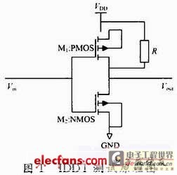
When the circuit is working normally, the static current is very small, but the static current of the defective circuit is very large, so when the static current in the circuit is detected to be abnormal, it can be determined that the circuit has a fault. This is also the principle of IDDQ testing. However, some faults in CMOS circuits, such as open circuit faults, do not cause abnormal static current. Therefore, it is necessary to introduce dynamic current testing. Based on this, this paper considers the combination of static current and dynamic current testing, rather than simply static current testing. IDDT is a short-term conduction current, that is, during the state transition of the CMOS circuit, the PMOS transistor and the NMOS transistor are turned on at the same time, so that a conduction circuit is formed between the power supply and the ground, as shown in Figure 1. Since IDDT is the change of current in the circuit during the dynamic transition, the size of IDDQ does not affect its result. Therefore, this also avoids the impact of the growing static leakage current of deep submicron circuits on the test. This paper studies the important significance of the combination of the two in hybrid circuit fault diagnosis.
2 Wavelet Neural Network for Hybrid Circuit Fault Diagnosis
Wavelet Neural Network is a combination of wavelet analysis theory and artificial neural network ANN theory. At present, there are two ways to combine the two:
(1) Loose combination. That is, wavelet analysis is used as a pre-processing method for neural networks to provide input feature vectors for neural networks.
(2) Compact combination. Wavelets and neural networks are directly fused, that is, wavelet functions and scaling functions form neurons.
This paper adopts a loose combination of wavelets and neural networks. First, the normal circuit and the fault circuit are modeled and simulated by PSPICE, and the static current IDDQ and dynamic current IDDT parameters are extracted. Wavelet analysis is used in Matlab to extract the characteristics of the obtained current, and a specific analysis is performed in combination with the neural network. The steps are as follows:
(1) Parameter extraction. The current information of the normal circuit and the circuit with various faults such as bridge faults and open circuit faults is extracted in PSPICE.
(2) Wavelet analysis. The current information obtained in (1) is decomposed by wavelet in Matlab, the wavelet coefficients are extracted, and the RMS is further calculated.
(3) Fault location. The wavelet analysis is combined with the BP neural network to analyze and judge its location effect. The specific steps are shown in Figure 2.

3 Hybrid circuit fault diagnosis example
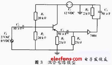
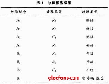
In PSPICE, a hybrid circuit composed of 7404 and a common collector amplifier circuit is used to study the fault model. The circuit model is shown in Figure 3. Through sensitivity analysis, it can be seen that R1, R2, R5, and C1 have a greater impact on the circuit. Four bridge faults and four open circuit faults are set in the circuit, as shown in Table 1. Although the production process leads to various circuit defects, various fault models can be used to equalize them according to the failure mechanism of various defects. For bridge faults, this paper uses a resistor connected between the bridge points to establish a fault model, and the resistance values are 10 Ω, 1 kΩ and 1 MΩ to correspond to relatively small, approximately equal, and relatively large. For open circuit faults, a 10 MΩ point resistor is connected to the open circuit point to establish a fault model.
3.1 Application of IDDQ in hybrid circuit fault detection
By simulating each fault model in PSPICE, the static current value can be easily obtained. IDDQ can clearly see the difference in leakage current for bridge faults in hybrid circuits, but it cannot detect open circuit faults. [page]
3.2 Application of IDDT in hybrid circuit fault detection
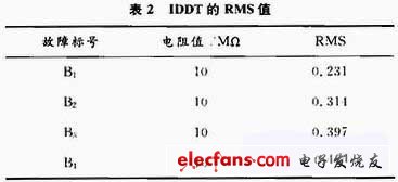
For the dynamic current information of normal circuits and open circuit faults obtained in PSPICE, a 5-layer wavelet transform is performed in Matlab to obtain the wavelet coefficients. The root mean square error is then used to reflect the difference between them. The root mean square error is defined by formula (1):

Where: Fi is the wavelet coefficient of the open circuit fault; Gi is the wavelet coefficient of the normal circuit; N is the number of wavelet coefficients. The RMS value is obtained by formula (1), see Table 2.
Therefore, through the analysis of the previous two sections, it can be seen that the combination of static current test and dynamic current test can significantly improve the fault coverage of the hybrid circuit, which has a certain guiding significance for the future diagnosis of hybrid circuit faults.
3.3 Combination of wavelet feature extraction and BP neural network
(1) Extraction of energy features. The current information of the circuit is decomposed by 5 layers of wavelets to obtain high-frequency wavelet decomposition coefficients and low-frequency wavelet decomposition coefficient vectors (d5, ..., d1, a5). Among them, the extraction of high-frequency coefficients uses the detcoef function in Matlab, while the extraction of low-frequency coefficients uses the appcoef function. Then combine the coefficient vectors into an energy feature vector:
F = (Ed5...Ed1, Ea5)
(2) Determine the structure and parameters of the BP neural network. The number of input neurons of the BP neural network is determined by the test node; the number of hidden layers can be roughly estimated by the "trial and error method" and formula (2).
In the formula: m, n and l are the number of hidden layer nodes, input nodes and output nodes respectively; a is an uncertain number between 1 and 10.
After repeated experiments, the BP neural network results of this paper are 6-7-4.
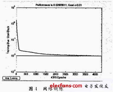
(3) Training the BP neural network. During the circuit simulation, 20 Monte Carlo analyses are performed to generate 20 samples, 10 of which are training samples and the other 10 are test samples. A total of 4 groups of training are required in this paper. The network training error curve is shown in Figure 4. It can be seen from the figure that the network has reached the target error after 4432 steps of training.
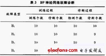
(4) Test the BP neural network to verify the trained BP neural network. The results are shown in Table 3. The detection rate of the wavelet neural network in this paper reaches 95%.
4 Conclusions and Prospects
Traditional fault diagnosis methods such as fault dictionaries, sensitivity-based analysis methods, and sub-network tearing methods can solve some tests and diagnosis. However, with the widespread application of mixed-signal circuits, high reliability has put forward higher requirements for fault diagnosis. Through this project, we first learned that the combination of static current testing and dynamic current testing can significantly improve the fault coverage of hybrid circuits; secondly, the combination of wavelet neural networks is significantly better than the single neural network method for fault location. From the latest literature, we can also clearly know that combining two or more fault diagnosis methods has become a development trend in hybrid circuit fault diagnosis.
Although this project has improved the fault diagnosis rate of hybrid circuits, the production of test vectors, unified modeling of hybrid circuits, and unified analysis of test responses are still severe challenges for hybrid circuit fault diagnosis.
Reference address:Fault Diagnosis of Hybrid Circuits Based on Current Testing
With the rapid development of electronic technology and the continuous improvement of manufacturing technology, the complexity of circuits has continued to increase, and the chip size has been reduced, so that more and more mixed signal circuits are integrated on the system-level chip, rather than just digital circuits or analog circuits. Due to the different test methods for digital and analog circuits, traditional testing can no longer meet the needs of development, which has brought unprecedented challenges to the designers, users, and maintainers of instruments and equipment, and has also made the detection of digital/analog mixed signal circuits increasingly highly valued by industry insiders. The mixed circuit fault diagnosis based on current testing proposed in this paper is proposed in this context.
1 Theoretical knowledge of current testing
Current testing refers to the detection and location of circuit faults by measuring the power supply current and effectively extracting the fault information of the circuit from it. It includes static current testing technology IDDQ and dynamic current testing technology IDDT.
When the circuit is working normally, the static current is very small, but the static current of the defective circuit is very large, so when the static current in the circuit is detected to be abnormal, it can be determined that the circuit has a fault. This is also the principle of IDDQ testing. However, some faults in CMOS circuits, such as open circuit faults, do not cause abnormal static current. Therefore, it is necessary to introduce dynamic current testing. Based on this, this paper considers the combination of static current and dynamic current testing, rather than simply static current testing. IDDT is a short-term conduction current, that is, during the state transition of the CMOS circuit, the PMOS transistor and the NMOS transistor are turned on at the same time, so that a conduction circuit is formed between the power supply and the ground, as shown in Figure 1. Since IDDT is the change of current in the circuit during the dynamic transition, the size of IDDQ does not affect its result. Therefore, this also avoids the impact of the growing static leakage current of deep submicron circuits on the test. This paper studies the important significance of the combination of the two in hybrid circuit fault diagnosis.

2 Wavelet Neural Network for Hybrid Circuit Fault Diagnosis
Wavelet Neural Network is a combination of wavelet analysis theory and artificial neural network ANN theory. At present, there are two ways to combine the two:
(1) Loose combination. That is, wavelet analysis is used as a pre-processing method for neural networks to provide input feature vectors for neural networks.
(2) Compact combination. Wavelets and neural networks are directly fused, that is, wavelet functions and scaling functions form neurons.
This paper adopts a loose combination of wavelets and neural networks. First, the normal circuit and the fault circuit are modeled and simulated by PSPICE, and the static current IDDQ and dynamic current IDDT parameters are extracted. Wavelet analysis is used in Matlab to extract the characteristics of the obtained current, and a specific analysis is performed in combination with the neural network. The steps are as follows:
(1) Parameter extraction. The current information of the normal circuit and the circuit with various faults such as bridge faults and open circuit faults is extracted in PSPICE.
(2) Wavelet analysis. The current information obtained in (1) is decomposed by wavelet in Matlab, the wavelet coefficients are extracted, and the RMS is further calculated.
(3) Fault location. The wavelet analysis is combined with the BP neural network to analyze and judge its location effect. The specific steps are shown in Figure 2.

3 Hybrid circuit fault diagnosis example
In PSPICE, a hybrid circuit composed of 7404 and a common collector amplifier circuit is used to study the fault model. The circuit model is shown in Figure 3. Through sensitivity analysis, it can be seen that R1, R2, R5, and C1 have a greater impact on the circuit. Four bridge faults and four open circuit faults are set in the circuit, as shown in Table 1. Although the production process leads to various circuit defects, various fault models can be used to equalize them according to the failure mechanism of various defects. For bridge faults, this paper uses a resistor connected between the bridge points to establish a fault model, and the resistance values are 10 Ω, 1 kΩ and 1 MΩ to correspond to relatively small, approximately equal, and relatively large. For open circuit faults, a 10 MΩ point resistor is connected to the open circuit point to establish a fault model.


3.1 Application of IDDQ in hybrid circuit fault detection
By simulating each fault model in PSPICE, the static current value can be easily obtained. IDDQ can clearly see the difference in leakage current for bridge faults in hybrid circuits, but it cannot detect open circuit faults. [page]
3.2 Application of IDDT in hybrid circuit fault detection
For the dynamic current information of normal circuits and open circuit faults obtained in PSPICE, a 5-layer wavelet transform is performed in Matlab to obtain the wavelet coefficients. The root mean square error is then used to reflect the difference between them. The root mean square error is defined by formula (1):

Where: Fi is the wavelet coefficient of the open circuit fault; Gi is the wavelet coefficient of the normal circuit; N is the number of wavelet coefficients. The RMS value is obtained by formula (1), see Table 2.

Therefore, through the analysis of the previous two sections, it can be seen that the combination of static current test and dynamic current test can significantly improve the fault coverage of the hybrid circuit, which has a certain guiding significance for the future diagnosis of hybrid circuit faults.
3.3 Combination of wavelet feature extraction and BP neural network
(1) Extraction of energy features. The current information of the circuit is decomposed by 5 layers of wavelets to obtain high-frequency wavelet decomposition coefficients and low-frequency wavelet decomposition coefficient vectors (d5, ..., d1, a5). Among them, the extraction of high-frequency coefficients uses the detcoef function in Matlab, while the extraction of low-frequency coefficients uses the appcoef function. Then combine the coefficient vectors into an energy feature vector:
F = (Ed5...Ed1, Ea5)
(2) Determine the structure and parameters of the BP neural network. The number of input neurons of the BP neural network is determined by the test node; the number of hidden layers can be roughly estimated by the "trial and error method" and formula (2).
In the formula: m, n and l are the number of hidden layer nodes, input nodes and output nodes respectively; a is an uncertain number between 1 and 10.
After repeated experiments, the BP neural network results of this paper are 6-7-4.
(3) Training the BP neural network. During the circuit simulation, 20 Monte Carlo analyses are performed to generate 20 samples, 10 of which are training samples and the other 10 are test samples. A total of 4 groups of training are required in this paper. The network training error curve is shown in Figure 4. It can be seen from the figure that the network has reached the target error after 4432 steps of training.

(4) Test the BP neural network to verify the trained BP neural network. The results are shown in Table 3. The detection rate of the wavelet neural network in this paper reaches 95%.

4 Conclusions and Prospects
Traditional fault diagnosis methods such as fault dictionaries, sensitivity-based analysis methods, and sub-network tearing methods can solve some tests and diagnosis. However, with the widespread application of mixed-signal circuits, high reliability has put forward higher requirements for fault diagnosis. Through this project, we first learned that the combination of static current testing and dynamic current testing can significantly improve the fault coverage of hybrid circuits; secondly, the combination of wavelet neural networks is significantly better than the single neural network method for fault location. From the latest literature, we can also clearly know that combining two or more fault diagnosis methods has become a development trend in hybrid circuit fault diagnosis.
Although this project has improved the fault diagnosis rate of hybrid circuits, the production of test vectors, unified modeling of hybrid circuits, and unified analysis of test responses are still severe challenges for hybrid circuit fault diagnosis.
Previous article:Design of automobile driving operation signal acquisition system based on MEMS gyroscope
Next article:Design of dynamic liquid level depth test system based on DSP
Recommended Content
Latest Test Measurement Articles
- Keysight Technologies Helps Samsung Electronics Successfully Validate FiRa® 2.0 Safe Distance Measurement Test Case
- From probes to power supplies, Tektronix is leading the way in comprehensive innovation in power electronics testing
- Seizing the Opportunities in the Chinese Application Market: NI's Challenges and Answers
- Tektronix Launches Breakthrough Power Measurement Tools to Accelerate Innovation as Global Electrification Accelerates
- Not all oscilloscopes are created equal: Why ADCs and low noise floor matter
- Enable TekHSI high-speed interface function to accelerate the remote transmission of waveform data
- How to measure the quality of soft start thyristor
- How to use a multimeter to judge whether a soft starter is good or bad
- What are the advantages and disadvantages of non-contact temperature sensors?
MoreSelected Circuit Diagrams
MorePopular Articles
- Innolux's intelligent steer-by-wire solution makes cars smarter and safer
- 8051 MCU - Parity Check
- How to efficiently balance the sensitivity of tactile sensing interfaces
- What should I do if the servo motor shakes? What causes the servo motor to shake quickly?
- 【Brushless Motor】Analysis of three-phase BLDC motor and sharing of two popular development boards
- Midea Industrial Technology's subsidiaries Clou Electronics and Hekang New Energy jointly appeared at the Munich Battery Energy Storage Exhibition and Solar Energy Exhibition
- Guoxin Sichen | Application of ferroelectric memory PB85RS2MC in power battery management, with a capacity of 2M
- Analysis of common faults of frequency converter
- In a head-on competition with Qualcomm, what kind of cockpit products has Intel come up with?
- Dalian Rongke's all-vanadium liquid flow battery energy storage equipment industrialization project has entered the sprint stage before production
MoreDaily News
- Allegro MicroSystems Introduces Advanced Magnetic and Inductive Position Sensing Solutions at Electronica 2024
- Car key in the left hand, liveness detection radar in the right hand, UWB is imperative for cars!
- After a decade of rapid development, domestic CIS has entered the market
- Aegis Dagger Battery + Thor EM-i Super Hybrid, Geely New Energy has thrown out two "king bombs"
- A brief discussion on functional safety - fault, error, and failure
- In the smart car 2.0 cycle, these core industry chains are facing major opportunities!
- The United States and Japan are developing new batteries. CATL faces challenges? How should China's new energy battery industry respond?
- Murata launches high-precision 6-axis inertial sensor for automobiles
- Ford patents pre-charge alarm to help save costs and respond to emergencies
- New real-time microcontroller system from Texas Instruments enables smarter processing in automotive and industrial applications
Guess you like
- Qorvo Online Design Conference - Rapid Customization of Power ICs Using ActiveCiPS Technology
- Switching Power Supply Primer
- [Perf-V Review] + Button Control RGB_LED Color Change
- MSP430 Program Library --- 12864 LCD Program Library
- TMS320F28027 ADC zero offset calibration
- Live broadcast at 14:00 this afternoon [Introduction and application of TI C2000 built-in programmable logic module CLB] (200 gifts)
- After the stepper motor is powered on according to the timing, it just shakes left and right and does not rotate. I would like some guidance.
- TI TMS320C6678 DSP + Xilinx Kintex-7 FPGA LED indicators and buttons
- Detailed explanation of the BLE connection establishment process
- Can't Allegro draw a rectangular box with Line attributes at one time?

 Feedback Control of Robot Driving Path


 京公网安备 11010802033920号