Chapter 5 Hardware Design and Software Design of Power Transformer DC Resistance Tester
Based on the improved method of combining the magnetic assist method with the constant current source proposed in the previous chapter, this paper uses a single-chip microcomputer to design a system to achieve rapid measurement of the DC resistance of the power transformer.
5.1 Hardware Design of the Power Transformer DC Resistance Tester
5.1.1 Overall system structure
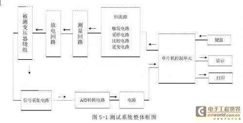
This device uses the 80C196 single-chip microcomputer as the core to form a single-chip microcomputer control unit, and completes the test and control functions through data storage and I/O port expansion. The overall structure of this test system is shown in Figure 5-1
The power supply part generates the microcontroller working power supply +5V and ±12V through a switching power supply. Among them, the relay working power supply +12V is stepped down by a transformer and rectified by a rectifier bridge. The keyboard has only four buttons, and the function selection is realized by pressing the buttons to complete the test, storage and printing functions. The test results are displayed and output through the LCD.
The microcontroller control unit is mainly based on the 80C196 microcontroller, with external expansion program memory EPROM27128, data memory RAM6264 and E2PROM2864, and the decoding circuit is realized by two 74LS138s. The address latch is completed by 74LS373. The I/O port expansion is realized by an 8255, which realizes the control of the printer, the control of the output relay, the input of the keyboard and the control of the LCD display. The
constant current source circuit mainly consists of the sampling circuit and comparison circuit of the constant current source, which converts the AC power into DC power through the rectifier bridge, and finally realizes the steady current output in the range of 0.1A~10A through current adjustment and current feedback.
The measurement circuit mainly consists of a constant current source that outputs a stable current directly through the power transformer winding. No standard resistor is connected (the resistor is short-circuited with a relay) to measure the charging current. When the charging current reaches the set value, the relay is disconnected and the resistor is connected in series to the measurement circuit. In order to ensure the stability of the microcontroller power supply, the relay control power supply is powered separately.
Due to the existence of winding inductance, residual current will pose a threat to users and test equipment, so there must be a current discharge circuit. The current discharge circuit is composed of a discharge resistor and a reverse diode. When charging, the diode is turned off and the power supply charges the winding. When the power is off, the diode is turned on and the winding is discharged through the diode and the discharge resistor.
5.1.2 Microcontroller control unit circuit
The 80C196 single-chip microcomputer is particularly suitable for various automatic control systems, such as industrial process control systems, servo systems, distributed control systems, variable frequency speed control motor control systems, etc. It is also suitable for general signal processing systems and advanced intelligent instruments, as well as high-performance computer external device controllers and office automation equipment controllers. Compared with the MCS-51 series, the 80C196 single-chip microcomputer has improved performance in the following aspects: The arithmetic logic unit in the CPU does not use the conventional accumulator structure, but uses a register-register structure. The CPU operation directly faces the 256-byte register. The bottleneck effect of the accumulator in the general CPU structure is eliminated, and the operation speed and data throughput are improved.
24 bytes of the 256-byte register are dedicated registers. The remaining 232 bytes are general registers, and the number of general registers is far more than the number of registers in a general CPU. In this way, it is possible to specify special registers for local variables in each interrupt service program, eliminating the software overhead paid for protecting and restoring the register site during the interrupt service process, and greatly facilitating program design.
There is a set of more efficient and faster execution instruction systems. It can operate on signed and unsigned numbers; the execution time of 16-bit multiplication by 16-bit instruction is 14 state cycles, and the execution time of 32-bit division by 16-bit instruction is 26 state cycles; there are also instructions such as sign extension and data normalization (used in floating-point calculations). In addition, three-operand instructions greatly improve instruction efficiency. In addition
to the above points, the 80C196 microcontroller also integrates more abundant peripheral devices, such as clock generator, timer/counter, standard input/output port, full-duplex asynchronous serial input/output port, watchdog timer (Watchdog) to improve the system's anti-interference ability, analog/digital converter, high-speed input/output device, pulse width modulation output, etc.
5.1.2.1 Address allocation and decoding circuit
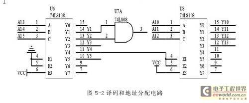
80C196 has a completely logically unified register space, that is, the program memory space, data memory space and I/O port are uniformly addressed, and the addressable range is 64KB. Therefore, in the design of the application system, the capacity of the program memory and data memory, the occupied addresses, the I/O ports and their addresses, and the expansion of other chips should be fully considered and arranged reasonably. This device uses more chips, so the decoding method is used for system expansion. The decoding circuit is composed of two 3/8 decoders 74LS138, as shown in Figure 5-2
5.1.2.2 External Memory Expansion
80C196 does not have an internal ROM. When designing an application system, an external program memory expansion must be performed to store user programs, etc. Considering the size of the application, EPROM27128 is selected as the program memory. In the expansion connection with the 80C196 microcontroller, the EPROM connection mainly consists of three types: address line, data line and control line. As shown in Figure 5-3
In the 80C196 single-chip computer, the P4 port is used as the address bus, responsible for transmitting the high 8-bit address code, and the P3 port is used as the address/data bus. When P3 and P4 jointly specify the address, P3 will also become the data bus. The control lines of EPROM mainly include: chip select line and output enable line. The chip select line is directly connected to the phase and output of Y1 and Y2, and the address is 2000H-5FFFH. The output enable line is directly connected to the read enable signal. When the chip select line of EPROM is low, the chip is enabled. During the valid period of the read signal, the EPROM output enable is valid. The program code of a specified unit is on the data bus. When the rising edge of the read signal appears, the CPU reads this data. The
80C196 single-chip computer has only 256 bytes of RAM inside, including 24 bytes of SFR (special registers). The stack pointer occupies 2 bytes. The capacity of the data memory is far from enough, so it is necessary to expand the external data memory. This device uses 6264 as the external data memory. The connection method of 6264 data line and address line is the same as that of EPROM. The control line has two chip select terminals and read/write signal lines. One of the two chip select terminals, CS2, is connected to the positive power supply VCC, and the other is connected to the chip select signal Y3.
E2PROM is an electrically erasable programmable read-only memory. Its main advantages are that it can be automatically erased and rewritten online, and it can save data in the event of a power outage without the need for a protective power supply. This device uses 2864 as the E2PROM , and its connection method is the same as that of RAM.
5.1.2.3 I/O expansion circuit
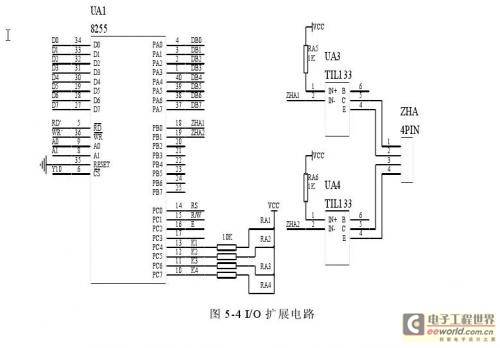
The 80C196 single-chip microcomputer has few I/O port lines. In this device, the display, keyboard and relay control all need to occupy port addresses, so the I/O port must be expanded. 8255 is widely used in single-chip microcomputer application systems. It contains three ports and has three working modes. Because of its programming selection, it is flexible and convenient to use and has strong versatility. In this device, a 8255 is selected for I/O port expansion. The circuit is shown in Figure 5-4 [page]
5.1.3 Discharge circuit
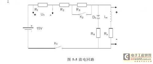
The circuit diagram of the discharge circuit is shown in Figure 5-5
At the end of the measurement, the relay K1 is disconnected. Because the transformer winding has a large inductance, the current cannot drop to zero immediately, which will generate a large potential e=Lx×(di/dt). Therefore, a discharge circuit must be added. In this discharge circuit, when the relay K1 is disconnected, the diode D1 is turned on, and the current in the winding forms a circuit through the discharge resistor R4 and the diode to complete the discharge process. The discharge resistor should be selected appropriately. The larger the discharge resistor, the more power consumed by the resistor, the shorter the discharge time, and the higher the voltage at both ends of the discharge circuit. Therefore, the selection of the discharge resistor should not only control the discharge voltage value to be safe, but also make the discharge time as short as possible.
5.1.4 Signal acquisition circuit
Signal acquisition is for the 80C196 single-chip microcomputer. In order to realize the display and protection of measurement results, a sampling and calculation circuit is required. On the one hand, the 8-channel 10-bit A/D converter of the 80C196 single-chip microcomputer and the calculation and processing function of the CPU can be used. On the other hand, a separate A/D converter device can be used, and AD1674 is selected. However, the signal entering the A/D converter and the single-chip microcomputer must be a conditioned signal [29], which requires the following conditions to be met:
(1) The signal amplitude cannot exceed ±5V;
(2) The signal entering the AD1674 and the microcontroller input port is a voltage signal;
(3) The input signal cannot interfere with the normal operation of the system;
Therefore, the signals entering AD1674 and the single-chip microcomputer must be properly processed. There are two types of electrical signals: current and voltage signals. The current signal must be converted into a voltage signal before entering the AD1674 and the single-chip microcomputer, which can be achieved using a resistor; high-voltage and alternating signals must be converted into low voltage before entering the single-chip microcomputer.
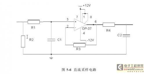
In this design, DC sampling is used. The voltage at both ends of the transformer winding under test is sent to the acquisition port of AD1674 through filtering, amplification, and buffering. R and C filtering are used for filtering, and voltage followers are used for buffering, as shown in Figure 5-6
5.1.5 A/D conversion of signals
The signal A/D conversion circuit uses AD1674. The structural characteristics and performance parameters of AD1674 are as follows
(1) 12-bit successive approximation ADC, can be selected to work in 12-bit or 8-bit.
(2) It has a three-state controllable output buffer, and the digital logic input and output level is TTL level.
(3) 12-bit data can be read out once or twice, which is convenient for connecting with 8-bit and 16-bit microcomputers.
(4) It has an internal voltage reference source of +10.00V, with a maximum error of +1.2%, and can output 1.5mA current.
(5) It has an internal clock generation circuit and does not require external wiring.
(6) It can be unipolar or bipolar analog input. When unipolar, the full scale is 0V~+10V and 0V~+20V, input from different pins. When bipolar input, the full scale is 0V~+5V and 0V~+10V, input from different pins.
(7) When unipolar input, the output digital quantity is the original code. When bipolar output, the output is offset binary code.
AD1674 can realize unipolar input or bipolar input through appropriate external connections. The input signals are all based on the analog AGND. One end of the analog input signal must be connected to AG, and the connection point should be as close to the AGND pin as possible, and the wiring should be short. The 10V reference voltage output pin REFOUT on the chip is also based on AGND. Usually the digital ground DGND is connected to AGND. All potentiometers (for gain adjustment and zero point adjustment) should use low temperature coefficient potentiometers. For example, metal mold ceramic potentiometers.
5.1.6 Printer interface
At present, among the micro-printers configured for single-chip application systems [31], the more popular ones are the TPμP series of dot matrix micro-printers. This type of printer is small in size, light in weight, has complete functions, is easy to operate and connect. The TPμP-A40P printer from this series is selected, which is a panel-type ultra-small dot matrix universal printer. "TP" is a trademark, "μP" means micro-printer, "A" means panel type, "40" means that a maximum of 40 characters can be printed per line, and the last character "P" means that the interface is a parallel interface. The basic parameters are as follows: Print width: 40 characters/line Printer interface: CENTRONICS parallel interface Print speed: 0.4 lines/second Power supply: DC +5V, current 1.5A Dimensions: 107*65*80mm 3
Previous article:A fast method for measuring the DC resistance of power transformers - software design
Next article:Fast Measurement Method of DC Resistance of Power Transformer-Dynamic Measurement Method
- Keysight Technologies Helps Samsung Electronics Successfully Validate FiRa® 2.0 Safe Distance Measurement Test Case
- From probes to power supplies, Tektronix is leading the way in comprehensive innovation in power electronics testing
- Seizing the Opportunities in the Chinese Application Market: NI's Challenges and Answers
- Tektronix Launches Breakthrough Power Measurement Tools to Accelerate Innovation as Global Electrification Accelerates
- Not all oscilloscopes are created equal: Why ADCs and low noise floor matter
- Enable TekHSI high-speed interface function to accelerate the remote transmission of waveform data
- How to measure the quality of soft start thyristor
- How to use a multimeter to judge whether a soft starter is good or bad
- What are the advantages and disadvantages of non-contact temperature sensors?
- Innolux's intelligent steer-by-wire solution makes cars smarter and safer
- 8051 MCU - Parity Check
- How to efficiently balance the sensitivity of tactile sensing interfaces
- What should I do if the servo motor shakes? What causes the servo motor to shake quickly?
- 【Brushless Motor】Analysis of three-phase BLDC motor and sharing of two popular development boards
- Midea Industrial Technology's subsidiaries Clou Electronics and Hekang New Energy jointly appeared at the Munich Battery Energy Storage Exhibition and Solar Energy Exhibition
- Guoxin Sichen | Application of ferroelectric memory PB85RS2MC in power battery management, with a capacity of 2M
- Analysis of common faults of frequency converter
- In a head-on competition with Qualcomm, what kind of cockpit products has Intel come up with?
- Dalian Rongke's all-vanadium liquid flow battery energy storage equipment industrialization project has entered the sprint stage before production
- Allegro MicroSystems Introduces Advanced Magnetic and Inductive Position Sensing Solutions at Electronica 2024
- Car key in the left hand, liveness detection radar in the right hand, UWB is imperative for cars!
- After a decade of rapid development, domestic CIS has entered the market
- Aegis Dagger Battery + Thor EM-i Super Hybrid, Geely New Energy has thrown out two "king bombs"
- A brief discussion on functional safety - fault, error, and failure
- In the smart car 2.0 cycle, these core industry chains are facing major opportunities!
- The United States and Japan are developing new batteries. CATL faces challenges? How should China's new energy battery industry respond?
- Murata launches high-precision 6-axis inertial sensor for automobiles
- Ford patents pre-charge alarm to help save costs and respond to emergencies
- New real-time microcontroller system from Texas Instruments enables smarter processing in automotive and industrial applications
- [Repost] "Very Silly" Circuit Problem
- E840-DTU device connection to Alibaba Cloud test
- Interface corresponding to SNVS_TAMPER3 signal
- Looking for a good and available domestic accelerometer
- nRF52832-QFAA Hardware Reference Design
- How to design the MCU+8266 program structure
- 【RPi PICO】Snapshot of the RP2040 chip
- Why does TIM1_CH3N not output PWM after configuring PWM in STM32F103C8T6?
- Please advise on the PinMux code
- Can you recommend a chip that can boost 3.3V to 5V?


 ICCV2023 Paper Summary: Efficient and Scalable Vision
 開關電源專業英語
 LTM8068 2.8VIN to 40VIN Isolated µModule DC/DC Converter with LDO Post Regulator Data Sheet


 京公网安备 11010802033920号