With the rapid development of manufacturing industries such as aviation, aerospace and automobile, the processing and precision evaluation of high-precision, complex and large parts have become a prominent issue of concern in the industry. Usually, such workpiece products need to undergo multiple processing-measurement-finishing to meet the design requirements. As a high-efficiency and high-precision manufacturing equipment, CNC machine tools have been widely used in manufacturing enterprises and are developing in the direction of high precision, high efficiency, openness, intelligence and integration. The goal of integration is to complete all or most of the processing tasks on a machine tool with one clamping as much as possible to ensure the position accuracy of the workpiece and improve production efficiency [1]. In addition, people continue to pursue high precision and high efficiency in workpiece processing. Online measurement technology integrated with CNC machine tools has received widespread attention in actual production. The
traditional offline measurement method, that is, the detection method of disassembling the moving workpiece, involves the problem of secondary clamping and positioning, resulting in poor consistency between the processing results and the measurement results, resulting in extended production cycles and reduced production efficiency. The detection method of disassembling the moving workpiece is the main reason hindering the improvement of the overall efficiency of digital manufacturing [2]. Online measurement is a detection method in which both the machining and measurement processes are carried out on the same device [3]. The workpiece can be processed and measured after one clamping, avoiding the positioning error of the secondary clamping, reducing the measurement cost, reducing the production auxiliary time, and improving the production efficiency and machining accuracy. The online measurement technology of CNC machine tools has the characteristics of fast sampling speed and high accuracy, and realizes the digital data acquisition and accuracy evaluation of the workpiece [4].
Compared with the three-dimensional coordinate measuring machine (CMM), the online measurement environment of CNC machine tools is complex and there are many factors affecting the error. However, the three-dimensional coordinate measuring machine is expensive, and the cost performance and the wide application are far less than those of CNC machine tools [5]. Therefore, when the accuracy requirement is not very high, the online measurement technology of CNC machine tools is more advantageous. The online measurement technology of CNC machine tools
is an important part of the integrated machining and measurement technology. It can expand the functions of CNC machine tools, effectively improve the use value of existing machine tools, and ensure the machining quality of parts [1, 6, 7]. Therefore, online measurement of CNC machine tools has been valued and applied by modern manufacturing enterprises, and has important research and application value. Domestic and foreign researchers have conducted a lot of research work in this regard and promoted and applied it in practice [8].
Composition and structure of online measurement of machine tools
Modern CNC machine tools have greatly improved in openness compared with the past. The good scalability and compatibility of modern CNC systems make it possible for a CNC machine tool to have a certain precision of three-dimensional coordinate measurement function [6, 9-10]. If the machine tool and the measurement system are organically integrated, the workpiece can be measured online while the parts are being processed.
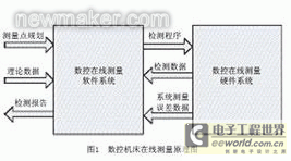
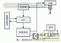
The composition of the CNC online measurement system mainly includes hardware and software. Similar to the CNC machining system, its hardware system mainly includes the CNC machine tool system and the probe system; the software system uses secondary development technology to realize online measurement programming similar to CNC machining programming, and obtains the NC code that drives the CNC machine tool to achieve measurement [11]. The principle diagram of the CNC machine tool online measurement system is shown in Figure 1.
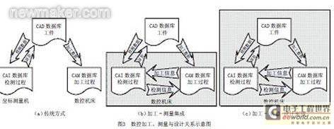
Although online measurement of CNC machine tools has many advantages, the existing online measurement systems are mostly dedicated and have a single measurement function, which cannot meet the complexity and diversity requirements of machined parts. Based on the machine tool online measurement system, it is integrated with the CAD system. After secondary development of the CAD system, measurement programming and simulation verification are realized, which increases the flexibility and working range of CNC machine tool online measurement and realizes the integration of design + processing + measurement (Design-Manufacturing-Inspection, referred to as DMI). The integrated schematic diagram of CNC processing, measurement and design at different stages is shown in Figure 3.
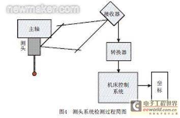
The key component that directly affects the accuracy of the online detection
system is the probe [6]. The trigger probe with the ability to search and advance is the most commonly used [7, 13-14], which provides a trigger signal to the CNC system to obtain the coordinates of the trigger point [9, 13]. One of the most critical functions of the probe system is that it can generate program interrupt instructions. When the probe tip contacts the workpiece to be measured, the probe system sends an external interrupt request to the CNC machine tool (the interrupt request is provided by the probe trigger signal). When the machine tool control system receives the interrupt, it latches the coordinate value of the center of the probe tip through the positioning system to determine the coordinate value of the contact point between the probe tip and the workpiece to be measured. The detection process of the probe system is shown in Figure 4.
Online detection movement is achieved through the control of the CNC detection program input into the CNC system. Due to the different CNC systems used in CNC machine tools, their control methods and programming codes are different.
2 Probe positioning
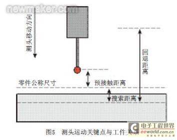
In order for the CNC machine tool to complete each online measurement accurately, efficiently and quickly, multiple measurement triggers are required in a measurement task. According to the movement of the probe during a measurement process, three distances need to be set [15], as shown in Figure 5. [page]
(2) Search distance. This distance sets the maximum distance that the probe can enter from the nominal size of the part in the direction of entering the material of the part being measured. If the probe is triggered during this distance, the machine tool will lock the coordinates of the trigger point. During the search distance stage, the probe should move at a given measurement speed.
(3) Retraction distance. This distance is the distance the probe retracts in the opposite direction after contacting the surface being measured. After the probe contacts the surface being measured, in order to avoid excessive movement and breakage, the probe needs to retract a certain distance in the opposite direction. At the same time, the retraction distance must be large enough to ensure that the probe can safely reach the next pre-contact point or positioning point. During the retraction distance stage, the probe retracts at the retraction speed.
In order to meet the different needs of the probe in each movement stage, three distances are corresponding to the measurement process, including three speeds, namely positioning speed, measurement speed and retraction speed. The measurement speed should be small to reduce the error of the measured value and avoid breaking the probe rod. To improve the measurement efficiency during the measurement process, the positioning speed and retraction speed can be set to large values to ensure that the probe moves at a faster speed and reduce the measurement time.
To avoid the probe breaking the probe rod by moving forward after touching the measured surface, the machine tool measurement will delete the remaining stroke after receiving the trigger signal. The remaining stroke deletion means that when the probe receives a trigger signal during the programmed stroke movement, it records the current coordinate value and skips the unfinished action and continues to execute the next line of code.
At present, CNC systems generally provide basic measurement instructions, or the development unit or personnel of the measurement system will also provide some packaged measurement instructions for users to use.
3 Inspection path planning
The CNC machine tool online measurement system is a system that performs measurement by sampling [16]. Therefore, the number and distribution of sampling points will directly affect the measurement results, which is particularly important for the measurement of free-form surfaces. It is unrealistic to sample the entire measured surface. In order to improve the reliability of the measurement results, the number of inspection points is usually increased, but while achieving high accuracy, it will also greatly reduce the measurement efficiency. Therefore, how to plan an efficient and accurate detection path becomes the key.
When planning the detection path for online measurement of machine tools, the measurement efficiency should be improved as much as possible on the basis of meeting the measurement accuracy requirements, that is, on the premise of meeting the measurement accuracy, the shortest measurement path should be used to detect the least measurement points. Taking cylindrical surface measurement as an example, the probe is positioned on the center line of the surface, and a four-point measurement method can be used to obtain high-precision measurement results. This measurement method is also applicable to internal hole measurement. For detailed measurement paths, see reference [17].
Under the guidance of path planning requirements, there are already definite measurement path planning schemes for plane measurement, boss/groove measurement, and angle measurement. For details, see reference [17].
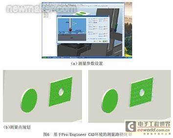
When performing complex measurements, programmers need to perform secondary development of the CAD system and perform human-computer interaction measurement path planning and programming in the CAD environment based on basic measurement principles. Figure 6 shows the measurement points and measurement paths planned by Harbin Institute of Technology based on secondary development of Pro/Engineer CAD environment for human-computer interaction.
In any measurement, due to the influence of various factors, the measured value will always have errors. In order to make the measurement result more accurately approach the true value, the measurement result needs to be compensated. Therefore, the error components that affect the measurement accuracy during the measurement process should be carefully analyzed and considered.
Since the online measurement system of CNC machine tools is based on the machine tool and integrated with the measurement system, the errors existing in the CNC machine tool processing process will also affect the measurement accuracy during the measurement process. The measurement errors of machine tool online measurement mainly include probe system errors, positioning errors of machine tool moving parts, and errors caused by unreasonable measurement paths [16]. Among them, the probe system error is further divided into probe static error, probe dynamic error, and probe installation error on the machine tool.
Probe static error includes dead zone error and probe repeatability error, which changes with the change of probe rod length, stiffness and contact pressure. Dead zone error refers to the bending deformation of the probe rod after the probe contacts the workpiece [18]. Probe repeatability error is relatively small compared to dead zone error, so probe static error is mainly determined by dead zone error. The dynamic error of the probe is mainly related to the contact speed during probe detection and the sampling interval of the CNC system.
The probe is installed on the machine tool spindle through the tool holder matched with the machine tool. Due to the incomplete alignment of the probe axis and the spindle axis, there is a probe installation error [3, 19], which causes measurement errors in multi-directional measurement. The misalignment installation error between the probe and the spindle can be partially compensated by calibrating the probe eccentricity before measurement.
Due to the manufacturing and assembly errors of CNC machine tool parts, the tracking error of the servo system, as well as factors such as clearance and friction, the various working parts of the machine tool will produce positioning errors during measurement movement.
In addition, the radius error of the probe is also a major error source, which can be eliminated by probe radius compensation during data processing [14]. However, in actual measurement, the situation is more complicated. The probe radius error will be introduced into the measurement result. In the measurement process of free-form surfaces, this error is more obvious.
In view of the many error sources in the measurement process, an efficient and high-precision error compensation algorithm is a key problem that needs to be solved urgently. In practical applications, multiple measurements and error compensation can be used to reduce measurement errors and improve measurement accuracy.
Integration of machine tool measurement system and CAD
As a typical representative of the MI mode, online measurement of CNC machine tools has greatly shortened the production cycle. However, in actual applications, due to the lack of connection with the design model of the parts, there are many inconveniences in interactive planning of the measurement path. In addition, when reprocessing based on the measurement results, errors will accumulate. After the DMI mode is integrated, the error can be compensated [20], thereby further improving the measurement accuracy.
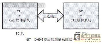
Given that the DMI mode has higher accuracy and flexibility than the MI mode of CNC machine tool online measurement system, we use the DMI mode of CNC machine tool online measurement and processing for the processing, measurement and finishing of complex parts to improve the measurement and processing accuracy. Connect the PC to the CNC machine tool, mainly complete the integration of the CAD system and the CAI software system on the PC, and complete the hardware system integration of the NC system and the CAI on the CNC machine tool, thereby realizing the integration of CAD/NC/CAI. The system structure is shown in Figure 7.
The operation steps of the machine tool online measurement system are as follows: the operator first loads the target part model into the virtual CNC operation environment; then the virtual operation environment is initialized, the purpose of which is to establish the relationship between the assembly coordinate system and the actual machine tool coordinate system in the virtual operation environment, and the transformation matrix of each moving part; finally, the operator selects the measurement surface selection, measurement path planning, measurement process simulation and other operations according to the function menu. When the part being processed (measured) needs to be modified, it is only necessary to activate the part in the virtual environment. After the modification is completed, the entire virtual environment is reactivated, and it can be operated again. The system integrates CAI operating software into the Pro/Engineer environment through secondary development technology, so that the CAD system and the CAI system can be seamlessly connected. The virtual measurement environment based on Pro/Engineer can simulate the actual operation process and verify the reliability of the measurement or processing process.
Conclusion
The machine tool online measurement system composed of the probe system and the CNC machine tool can significantly reduce the production auxiliary time, reduce the labor intensity of workers, and improve production efficiency. At the same time, it also reduces the scrap rate caused by offline measurement errors and gives full play to the performance of CNC machine tools. The application of machine tool measurement can reduce the intermediate links, ensure the processing accuracy, and improve the processing capacity of CNC machine tools; it can also realize the digital data collection of workpieces, and later on, it can also realize the three-dimensional reconstruction of the workpiece surface with the help of computer-aided design systems. The machine tool online measurement system based on the DMI mode can make full use of the powerful graphic interaction capabilities and design functions of CAD through secondary development of CAD, so that users can plan interactive measurement paths and facilitate the application of the system. The research and application system development in this direction have great application value and also improve the application level of CNC machine tools. (end)
Reference address:Research on Online Measurement Technology of CNC Machine Tools
traditional offline measurement method, that is, the detection method of disassembling the moving workpiece, involves the problem of secondary clamping and positioning, resulting in poor consistency between the processing results and the measurement results, resulting in extended production cycles and reduced production efficiency. The detection method of disassembling the moving workpiece is the main reason hindering the improvement of the overall efficiency of digital manufacturing [2]. Online measurement is a detection method in which both the machining and measurement processes are carried out on the same device [3]. The workpiece can be processed and measured after one clamping, avoiding the positioning error of the secondary clamping, reducing the measurement cost, reducing the production auxiliary time, and improving the production efficiency and machining accuracy. The online measurement technology of CNC machine tools has the characteristics of fast sampling speed and high accuracy, and realizes the digital data acquisition and accuracy evaluation of the workpiece [4].
Compared with the three-dimensional coordinate measuring machine (CMM), the online measurement environment of CNC machine tools is complex and there are many factors affecting the error. However, the three-dimensional coordinate measuring machine is expensive, and the cost performance and the wide application are far less than those of CNC machine tools [5]. Therefore, when the accuracy requirement is not very high, the online measurement technology of CNC machine tools is more advantageous. The online measurement technology of CNC machine tools
is an important part of the integrated machining and measurement technology. It can expand the functions of CNC machine tools, effectively improve the use value of existing machine tools, and ensure the machining quality of parts [1, 6, 7]. Therefore, online measurement of CNC machine tools has been valued and applied by modern manufacturing enterprises, and has important research and application value. Domestic and foreign researchers have conducted a lot of research work in this regard and promoted and applied it in practice [8].
Composition and structure of online measurement of machine tools
Modern CNC machine tools have greatly improved in openness compared with the past. The good scalability and compatibility of modern CNC systems make it possible for a CNC machine tool to have a certain precision of three-dimensional coordinate measurement function [6, 9-10]. If the machine tool and the measurement system are organically integrated, the workpiece can be measured online while the parts are being processed.
The composition of the CNC online measurement system mainly includes hardware and software. Similar to the CNC machining system, its hardware system mainly includes the CNC machine tool system and the probe system; the software system uses secondary development technology to realize online measurement programming similar to CNC machining programming, and obtains the NC code that drives the CNC machine tool to achieve measurement [11]. The principle diagram of the CNC machine tool online measurement system is shown in Figure 1.
Although online measurement of CNC machine tools has many advantages, the existing online measurement systems are mostly dedicated and have a single measurement function, which cannot meet the complexity and diversity requirements of machined parts. Based on the machine tool online measurement system, it is integrated with the CAD system. After secondary development of the CAD system, measurement programming and simulation verification are realized, which increases the flexibility and working range of CNC machine tool online measurement and realizes the integration of design + processing + measurement (Design-Manufacturing-Inspection, referred to as DMI). The integrated schematic diagram of CNC processing, measurement and design at different stages is shown in Figure 3.
The key component that directly affects the accuracy of the online detection
system is the probe [6]. The trigger probe with the ability to search and advance is the most commonly used [7, 13-14], which provides a trigger signal to the CNC system to obtain the coordinates of the trigger point [9, 13]. One of the most critical functions of the probe system is that it can generate program interrupt instructions. When the probe tip contacts the workpiece to be measured, the probe system sends an external interrupt request to the CNC machine tool (the interrupt request is provided by the probe trigger signal). When the machine tool control system receives the interrupt, it latches the coordinate value of the center of the probe tip through the positioning system to determine the coordinate value of the contact point between the probe tip and the workpiece to be measured. The detection process of the probe system is shown in Figure 4.
Online detection movement is achieved through the control of the CNC detection program input into the CNC system. Due to the different CNC systems used in CNC machine tools, their control methods and programming codes are different.
2 Probe positioning
In order for the CNC machine tool to complete each online measurement accurately, efficiently and quickly, multiple measurement triggers are required in a measurement task. According to the movement of the probe during a measurement process, three distances need to be set [15], as shown in Figure 5. [page]
(2) Search distance. This distance sets the maximum distance that the probe can enter from the nominal size of the part in the direction of entering the material of the part being measured. If the probe is triggered during this distance, the machine tool will lock the coordinates of the trigger point. During the search distance stage, the probe should move at a given measurement speed.
(3) Retraction distance. This distance is the distance the probe retracts in the opposite direction after contacting the surface being measured. After the probe contacts the surface being measured, in order to avoid excessive movement and breakage, the probe needs to retract a certain distance in the opposite direction. At the same time, the retraction distance must be large enough to ensure that the probe can safely reach the next pre-contact point or positioning point. During the retraction distance stage, the probe retracts at the retraction speed.
In order to meet the different needs of the probe in each movement stage, three distances are corresponding to the measurement process, including three speeds, namely positioning speed, measurement speed and retraction speed. The measurement speed should be small to reduce the error of the measured value and avoid breaking the probe rod. To improve the measurement efficiency during the measurement process, the positioning speed and retraction speed can be set to large values to ensure that the probe moves at a faster speed and reduce the measurement time.
To avoid the probe breaking the probe rod by moving forward after touching the measured surface, the machine tool measurement will delete the remaining stroke after receiving the trigger signal. The remaining stroke deletion means that when the probe receives a trigger signal during the programmed stroke movement, it records the current coordinate value and skips the unfinished action and continues to execute the next line of code.
At present, CNC systems generally provide basic measurement instructions, or the development unit or personnel of the measurement system will also provide some packaged measurement instructions for users to use.
3 Inspection path planning
The CNC machine tool online measurement system is a system that performs measurement by sampling [16]. Therefore, the number and distribution of sampling points will directly affect the measurement results, which is particularly important for the measurement of free-form surfaces. It is unrealistic to sample the entire measured surface. In order to improve the reliability of the measurement results, the number of inspection points is usually increased, but while achieving high accuracy, it will also greatly reduce the measurement efficiency. Therefore, how to plan an efficient and accurate detection path becomes the key.
When planning the detection path for online measurement of machine tools, the measurement efficiency should be improved as much as possible on the basis of meeting the measurement accuracy requirements, that is, on the premise of meeting the measurement accuracy, the shortest measurement path should be used to detect the least measurement points. Taking cylindrical surface measurement as an example, the probe is positioned on the center line of the surface, and a four-point measurement method can be used to obtain high-precision measurement results. This measurement method is also applicable to internal hole measurement. For detailed measurement paths, see reference [17].
Under the guidance of path planning requirements, there are already definite measurement path planning schemes for plane measurement, boss/groove measurement, and angle measurement. For details, see reference [17].
When performing complex measurements, programmers need to perform secondary development of the CAD system and perform human-computer interaction measurement path planning and programming in the CAD environment based on basic measurement principles. Figure 6 shows the measurement points and measurement paths planned by Harbin Institute of Technology based on secondary development of Pro/Engineer CAD environment for human-computer interaction.
In any measurement, due to the influence of various factors, the measured value will always have errors. In order to make the measurement result more accurately approach the true value, the measurement result needs to be compensated. Therefore, the error components that affect the measurement accuracy during the measurement process should be carefully analyzed and considered.
Since the online measurement system of CNC machine tools is based on the machine tool and integrated with the measurement system, the errors existing in the CNC machine tool processing process will also affect the measurement accuracy during the measurement process. The measurement errors of machine tool online measurement mainly include probe system errors, positioning errors of machine tool moving parts, and errors caused by unreasonable measurement paths [16]. Among them, the probe system error is further divided into probe static error, probe dynamic error, and probe installation error on the machine tool.
Probe static error includes dead zone error and probe repeatability error, which changes with the change of probe rod length, stiffness and contact pressure. Dead zone error refers to the bending deformation of the probe rod after the probe contacts the workpiece [18]. Probe repeatability error is relatively small compared to dead zone error, so probe static error is mainly determined by dead zone error. The dynamic error of the probe is mainly related to the contact speed during probe detection and the sampling interval of the CNC system.
The probe is installed on the machine tool spindle through the tool holder matched with the machine tool. Due to the incomplete alignment of the probe axis and the spindle axis, there is a probe installation error [3, 19], which causes measurement errors in multi-directional measurement. The misalignment installation error between the probe and the spindle can be partially compensated by calibrating the probe eccentricity before measurement.
Due to the manufacturing and assembly errors of CNC machine tool parts, the tracking error of the servo system, as well as factors such as clearance and friction, the various working parts of the machine tool will produce positioning errors during measurement movement.
In addition, the radius error of the probe is also a major error source, which can be eliminated by probe radius compensation during data processing [14]. However, in actual measurement, the situation is more complicated. The probe radius error will be introduced into the measurement result. In the measurement process of free-form surfaces, this error is more obvious.
In view of the many error sources in the measurement process, an efficient and high-precision error compensation algorithm is a key problem that needs to be solved urgently. In practical applications, multiple measurements and error compensation can be used to reduce measurement errors and improve measurement accuracy.
Integration of machine tool measurement system and CAD
As a typical representative of the MI mode, online measurement of CNC machine tools has greatly shortened the production cycle. However, in actual applications, due to the lack of connection with the design model of the parts, there are many inconveniences in interactive planning of the measurement path. In addition, when reprocessing based on the measurement results, errors will accumulate. After the DMI mode is integrated, the error can be compensated [20], thereby further improving the measurement accuracy.
Given that the DMI mode has higher accuracy and flexibility than the MI mode of CNC machine tool online measurement system, we use the DMI mode of CNC machine tool online measurement and processing for the processing, measurement and finishing of complex parts to improve the measurement and processing accuracy. Connect the PC to the CNC machine tool, mainly complete the integration of the CAD system and the CAI software system on the PC, and complete the hardware system integration of the NC system and the CAI on the CNC machine tool, thereby realizing the integration of CAD/NC/CAI. The system structure is shown in Figure 7.
The operation steps of the machine tool online measurement system are as follows: the operator first loads the target part model into the virtual CNC operation environment; then the virtual operation environment is initialized, the purpose of which is to establish the relationship between the assembly coordinate system and the actual machine tool coordinate system in the virtual operation environment, and the transformation matrix of each moving part; finally, the operator selects the measurement surface selection, measurement path planning, measurement process simulation and other operations according to the function menu. When the part being processed (measured) needs to be modified, it is only necessary to activate the part in the virtual environment. After the modification is completed, the entire virtual environment is reactivated, and it can be operated again. The system integrates CAI operating software into the Pro/Engineer environment through secondary development technology, so that the CAD system and the CAI system can be seamlessly connected. The virtual measurement environment based on Pro/Engineer can simulate the actual operation process and verify the reliability of the measurement or processing process.
Conclusion
The machine tool online measurement system composed of the probe system and the CNC machine tool can significantly reduce the production auxiliary time, reduce the labor intensity of workers, and improve production efficiency. At the same time, it also reduces the scrap rate caused by offline measurement errors and gives full play to the performance of CNC machine tools. The application of machine tool measurement can reduce the intermediate links, ensure the processing accuracy, and improve the processing capacity of CNC machine tools; it can also realize the digital data collection of workpieces, and later on, it can also realize the three-dimensional reconstruction of the workpiece surface with the help of computer-aided design systems. The machine tool online measurement system based on the DMI mode can make full use of the powerful graphic interaction capabilities and design functions of CAD through secondary development of CAD, so that users can plan interactive measurement paths and facilitate the application of the system. The research and application system development in this direction have great application value and also improve the application level of CNC machine tools. (end)
Previous article:Automated production requires automated measurement
Next article:Development of Online Measurement for Wire EDM
- Popular Resources
- Popular amplifiers
Recommended Content
Latest Test Measurement Articles
- Keysight Technologies Helps Samsung Electronics Successfully Validate FiRa® 2.0 Safe Distance Measurement Test Case
- From probes to power supplies, Tektronix is leading the way in comprehensive innovation in power electronics testing
- Seizing the Opportunities in the Chinese Application Market: NI's Challenges and Answers
- Tektronix Launches Breakthrough Power Measurement Tools to Accelerate Innovation as Global Electrification Accelerates
- Not all oscilloscopes are created equal: Why ADCs and low noise floor matter
- Enable TekHSI high-speed interface function to accelerate the remote transmission of waveform data
- How to measure the quality of soft start thyristor
- How to use a multimeter to judge whether a soft starter is good or bad
- What are the advantages and disadvantages of non-contact temperature sensors?
MoreSelected Circuit Diagrams
MorePopular Articles
- Innolux's intelligent steer-by-wire solution makes cars smarter and safer
- 8051 MCU - Parity Check
- How to efficiently balance the sensitivity of tactile sensing interfaces
- What should I do if the servo motor shakes? What causes the servo motor to shake quickly?
- 【Brushless Motor】Analysis of three-phase BLDC motor and sharing of two popular development boards
- Midea Industrial Technology's subsidiaries Clou Electronics and Hekang New Energy jointly appeared at the Munich Battery Energy Storage Exhibition and Solar Energy Exhibition
- Guoxin Sichen | Application of ferroelectric memory PB85RS2MC in power battery management, with a capacity of 2M
- Analysis of common faults of frequency converter
- In a head-on competition with Qualcomm, what kind of cockpit products has Intel come up with?
- Dalian Rongke's all-vanadium liquid flow battery energy storage equipment industrialization project has entered the sprint stage before production
MoreDaily News
- Allegro MicroSystems Introduces Advanced Magnetic and Inductive Position Sensing Solutions at Electronica 2024
- Car key in the left hand, liveness detection radar in the right hand, UWB is imperative for cars!
- After a decade of rapid development, domestic CIS has entered the market
- Aegis Dagger Battery + Thor EM-i Super Hybrid, Geely New Energy has thrown out two "king bombs"
- A brief discussion on functional safety - fault, error, and failure
- In the smart car 2.0 cycle, these core industry chains are facing major opportunities!
- The United States and Japan are developing new batteries. CATL faces challenges? How should China's new energy battery industry respond?
- Murata launches high-precision 6-axis inertial sensor for automobiles
- Ford patents pre-charge alarm to help save costs and respond to emergencies
- New real-time microcontroller system from Texas Instruments enables smarter processing in automotive and industrial applications
Guess you like
- Derivation of the voltage transfer function of a circuit containing capacitors T(S) = Vo(S)/Vi(S)
- Answer the question to win a prize | Using GaN technology to meet power adapter design challenges
- Question about the schematic diagram of switching power supply
- Application of NGI DC Power Supply in Current Sensor Testing
- It is said that Lichuang's server was hacked
- TI C6000 series DSP pipeline introduction and software pipeline optimization
- Material: RF Circuit Design - Theory and Application
- A Brief Analysis of Streaming Media Solutions Based on Embedded DSP
- Another TWS earphone charging box disassembly
- The official ST Chinese forum is now online. Let’s go and have a look.

 Overview of CNC Machine Tools
 Pitch Error Detection and Compensation for CNC Machine Tools


 京公网安备 11010802033920号