An ideal probe should be easy to connect, have reliable and secure contacts, not degrade the signal it transmits or cause distortion, have linear phase behavior, no attenuation, have unlimited bandwidth, high noise immunity, and not load the signal source. In practice, however, all of these properties are impossible to achieve absolutely and in some cases are far from the desired measurement situation. In practice, the signals to be measured are often difficult to access, their impedance variations can be very large, the overall setup is very noise-sensitive and frequency-dependent, the bandwidth is limited, and differences in signal propagation can cause slight timing deviations (phase and time deviations) between multiple measurement channels.
Fortunately, oscilloscope manufacturers have gone to great lengths to minimize probe-related effects, making them easier to connect to circuits and more reliable. For example, it is difficult to hold a probe in one hand while operating an oscilloscope with the other.
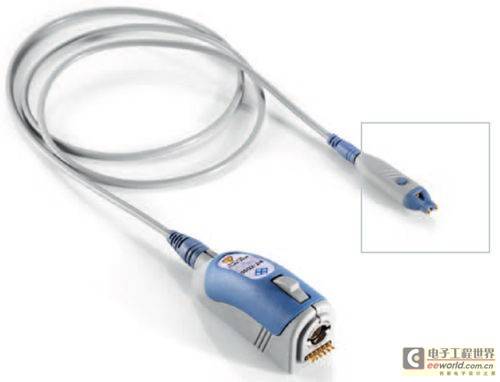
Therefore, the active probes of the R&S RTO oscilloscope series allow users to control oscilloscope functions with a single button on the probe, and include controls for many functions. The measuring instrument also features an integrated voltmeter called the R&S ProbeMeter, which allows more accurate DC measurements than conventional oscilloscope channels.
Voltage probes and AC or AC/DC current probes are two basic probe types. But there are many other probes designed for specific measurement tasks, including logic probes designed for troubleshooting the logic states of digital circuits. Environmental probes are designed to operate over a wide temperature range, while temperature probes can be used to measure the temperature of components and can be used in circuits where high temperatures are likely to occur. There are also probes designed to be used in wafer-level probing stations, as well as optical probes that convert light signals to electrical signals so that they can be viewed on an oscilloscope, and some specialized probes can be used to measure high voltages.
Oscilloscope Probe Classification
Passive Probes
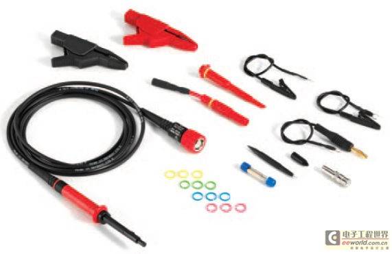
Passive probes are the simplest and least expensive type of probe and provide most of the necessary measurement capabilities. Passive probes are essentially wires and connectors, and when attenuation is required, they also have resistors and capacitors. There are no active components in passive probes, so they can operate without the need for power from the oscilloscope, making them inherently very durable.
1X ("single") probes are probes that have the same dynamic range as an oscilloscope, while attenuated probes extend the instrument's measurement range by attenuating signal levels by 10, 100, or even more times. The most common probe is the 10X type because it has a low loading effect and provides a larger voltage measurement range. The 10X probe is a typical "standard" probe for many instruments. A
1X passive high impedance probe connected to the 1M ohm input of an oscilloscope has a very high sensitivity (little attenuation), while a 10:1 passive high impedance probe connected to the 1M ohm input of an oscilloscope provides a wider dynamic range, higher input impedance, and lower capacitance than a 1X probe. A 10:1 passive low impedance probe connected to the 50 ohm input of an oscilloscope has almost no impedance change with frequency, but since its nominal impedance is 500 ohms, it will become a significant load on the signal source.
When the signal amplitude is quite low, a 1X probe is required; but for signals with mixed low and medium amplitude components, a 1X/10X attenuation ratio adjustable probe is more convenient. The typical bandwidth of a passive probe ranges from less than 100 MHz to 500 MHz. For high speed (high frequency) signals encountered in a 50 ohm environment, a 50 ohm probe is required with bandwidths up to several gigahertz and rise times of 100 ps or faster.
Passive probes include a low frequency adjustment control that is used when the probe is connected to an oscilloscope. Low frequency compensation is used to match the capacitance of the probe to the capacitance of the oscilloscope input. The high frequency adjustment control is only used for operating frequencies above 50 MHz. Passive probes from certain vendors for higher frequencies are factory adjusted, so only low frequency adjustments must be performed. Active probes do not require these types of adjustments because their properties and compensation are determined at the factory.
Active Probes
However, the integrated buffer amplifiers in active probes only work over a limited voltage range, and the impedance of active probes depends on the frequency of the signal. In addition, although active probes can be used to handle voltages of thousands of volts, they are active devices after all, and their mechanical reliability is not as good as that of passive probes.
Differential Probes
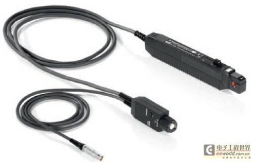
Current probe
High Voltage Probes
Probe Considerations
Circuit Loading
In practice, this may allow a circuit that is otherwise faulty to work properly, but more often it will cause the circuit to work incorrectly. To reduce the effects of resistive load, probes with a resistance value that is more than 10 times the resistance of the circuit being measured are generally used for measurement.
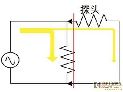
Capacitive load reduces the rise speed of the signal, reduces bandwidth, and increases transmission delay. Capacitive load is caused by the capacitance of the probe tip. It introduces frequency measurement errors and is the largest factor in delay and rise time measurements. Capacitive load is caused by the capacitance in the probe, which behaves as a high-pass filter at high frequencies, causing high-frequency information to flow through the ground wire, significantly reducing the input impedance of the probe at high frequencies. Therefore, probes with smaller tip capacitance are required.
Inductive loading also causes distortion in the measured signal and is caused by the inductance of the loop between the probe tip and the probe ground lead. The signal ringing caused by the inductive loading in the ground lead, together with the capacitance of the probe tip, can be mitigated by effective grounding, which can increase the oscillation frequency beyond the bandwidth of the instrument. The length of the ground lead should be kept as short as possible to reduce the length of the loop and thus minimize the inductance. Lower inductance minimizes the ringing on the top of the measured waveform.
Grounding
When making measurements with an oscilloscope, proper grounding is essential for accurate results and operator safety, especially when working with high voltages. The instrument must be grounded through the power cord and should never be operated with the "protective ground" disconnected. When the signal ground of the device under test causes a ground loop through the power ground at another location, this can cause unwanted low-frequency hum. A common solution is to isolate the signal ground from the power ground and then make a connection to the signal ground close to the signal pins.
Probe Selection Process
There are two most decisive factors in selecting the right (voltage) probe: the bandwidth required to capture the waveform without distortion, and the minimum impedance required to minimize circuit loading. The specified bandwidth of an oscilloscope applies only to a 50 ohm input impedance and a limited input voltage range. To maintain harmonic and waveform integrity, the bandwidth of the instrument must be at least five times the highest pulse frequency being measured.
For AC measurements, the specified DC impedance is very small. Impedance decreases as frequency increases, and passive probes decrease most significantly. By trying to keep the input impedance at 10 times the source impedance at the highest signal frequency, the choice between active and passive probes can be made. This can narrow the selection to just one or two probe models that best match the measurement setup requirements. For oscilloscope bandwidths in the microwave range, active probes will definitely have the greatest advantage.
Keep in mind that 10x passive probes have the highest impedance at low frequencies, and passive probes generally do not cause DC offsets or introduce noise. Active probes, on the other hand, provide constant impedance at frequencies of several kilohertz and have the highest impedance at frequencies of several hundred megahertz. Low impedance probes provide constant impedance up to 1 GHz, and while it is desirable to maintain constant impedance at a certain frequency, lower impedance avoids distortion of harmonic signals.
In short, active probes are recommended for signal frequency components above 100 MHz, and low input impedance results in higher resonant frequencies. Connections to active probes should be kept as short as possible to ensure a high usable bandwidth. In addition, if the ground level is unstable, a differential probe may be required.
For passive probes, it is important to use the probe model recommended for a particular instrument, even if the bandwidth specification of the probe is higher than required. Low input capacitance results in higher resonant frequencies. The ground lead should be kept as short as possible to reduce the inductance of the ground lead. Care must be taken when measuring steep rise times, as the resonant frequency can be much lower than the system bandwidth. The impedance of the probe should be approximately ten times the impedance of the circuit measurement point so as not to introduce too much loading to the circuit. (end)
Keywords:Oscilloscope
Reference address:A Brief Discussion on Oscilloscope Probes
Fortunately, oscilloscope manufacturers have gone to great lengths to minimize probe-related effects, making them easier to connect to circuits and more reliable. For example, it is difficult to hold a probe in one hand while operating an oscilloscope with the other.
Therefore, the active probes of the R&S RTO oscilloscope series allow users to control oscilloscope functions with a single button on the probe, and include controls for many functions. The measuring instrument also features an integrated voltmeter called the R&S ProbeMeter, which allows more accurate DC measurements than conventional oscilloscope channels.
Voltage probes and AC or AC/DC current probes are two basic probe types. But there are many other probes designed for specific measurement tasks, including logic probes designed for troubleshooting the logic states of digital circuits. Environmental probes are designed to operate over a wide temperature range, while temperature probes can be used to measure the temperature of components and can be used in circuits where high temperatures are likely to occur. There are also probes designed to be used in wafer-level probing stations, as well as optical probes that convert light signals to electrical signals so that they can be viewed on an oscilloscope, and some specialized probes can be used to measure high voltages.
Oscilloscope Probe Classification
Passive Probes
Passive probes are the simplest and least expensive type of probe and provide most of the necessary measurement capabilities. Passive probes are essentially wires and connectors, and when attenuation is required, they also have resistors and capacitors. There are no active components in passive probes, so they can operate without the need for power from the oscilloscope, making them inherently very durable.
1X ("single") probes are probes that have the same dynamic range as an oscilloscope, while attenuated probes extend the instrument's measurement range by attenuating signal levels by 10, 100, or even more times. The most common probe is the 10X type because it has a low loading effect and provides a larger voltage measurement range. The 10X probe is a typical "standard" probe for many instruments. A
1X passive high impedance probe connected to the 1M ohm input of an oscilloscope has a very high sensitivity (little attenuation), while a 10:1 passive high impedance probe connected to the 1M ohm input of an oscilloscope provides a wider dynamic range, higher input impedance, and lower capacitance than a 1X probe. A 10:1 passive low impedance probe connected to the 50 ohm input of an oscilloscope has almost no impedance change with frequency, but since its nominal impedance is 500 ohms, it will become a significant load on the signal source.
When the signal amplitude is quite low, a 1X probe is required; but for signals with mixed low and medium amplitude components, a 1X/10X attenuation ratio adjustable probe is more convenient. The typical bandwidth of a passive probe ranges from less than 100 MHz to 500 MHz. For high speed (high frequency) signals encountered in a 50 ohm environment, a 50 ohm probe is required with bandwidths up to several gigahertz and rise times of 100 ps or faster.
Passive probes include a low frequency adjustment control that is used when the probe is connected to an oscilloscope. Low frequency compensation is used to match the capacitance of the probe to the capacitance of the oscilloscope input. The high frequency adjustment control is only used for operating frequencies above 50 MHz. Passive probes from certain vendors for higher frequencies are factory adjusted, so only low frequency adjustments must be performed. Active probes do not require these types of adjustments because their properties and compensation are determined at the factory.
Active Probes

However, the integrated buffer amplifiers in active probes only work over a limited voltage range, and the impedance of active probes depends on the frequency of the signal. In addition, although active probes can be used to handle voltages of thousands of volts, they are active devices after all, and their mechanical reliability is not as good as that of passive probes.
Differential Probes

Current probe

High Voltage Probes

Probe Considerations
Circuit Loading

In practice, this may allow a circuit that is otherwise faulty to work properly, but more often it will cause the circuit to work incorrectly. To reduce the effects of resistive load, probes with a resistance value that is more than 10 times the resistance of the circuit being measured are generally used for measurement.
Capacitive load reduces the rise speed of the signal, reduces bandwidth, and increases transmission delay. Capacitive load is caused by the capacitance of the probe tip. It introduces frequency measurement errors and is the largest factor in delay and rise time measurements. Capacitive load is caused by the capacitance in the probe, which behaves as a high-pass filter at high frequencies, causing high-frequency information to flow through the ground wire, significantly reducing the input impedance of the probe at high frequencies. Therefore, probes with smaller tip capacitance are required.
Inductive loading also causes distortion in the measured signal and is caused by the inductance of the loop between the probe tip and the probe ground lead. The signal ringing caused by the inductive loading in the ground lead, together with the capacitance of the probe tip, can be mitigated by effective grounding, which can increase the oscillation frequency beyond the bandwidth of the instrument. The length of the ground lead should be kept as short as possible to reduce the length of the loop and thus minimize the inductance. Lower inductance minimizes the ringing on the top of the measured waveform.
Grounding
When making measurements with an oscilloscope, proper grounding is essential for accurate results and operator safety, especially when working with high voltages. The instrument must be grounded through the power cord and should never be operated with the "protective ground" disconnected. When the signal ground of the device under test causes a ground loop through the power ground at another location, this can cause unwanted low-frequency hum. A common solution is to isolate the signal ground from the power ground and then make a connection to the signal ground close to the signal pins.
Probe Selection Process
There are two most decisive factors in selecting the right (voltage) probe: the bandwidth required to capture the waveform without distortion, and the minimum impedance required to minimize circuit loading. The specified bandwidth of an oscilloscope applies only to a 50 ohm input impedance and a limited input voltage range. To maintain harmonic and waveform integrity, the bandwidth of the instrument must be at least five times the highest pulse frequency being measured.
For AC measurements, the specified DC impedance is very small. Impedance decreases as frequency increases, and passive probes decrease most significantly. By trying to keep the input impedance at 10 times the source impedance at the highest signal frequency, the choice between active and passive probes can be made. This can narrow the selection to just one or two probe models that best match the measurement setup requirements. For oscilloscope bandwidths in the microwave range, active probes will definitely have the greatest advantage.
Keep in mind that 10x passive probes have the highest impedance at low frequencies, and passive probes generally do not cause DC offsets or introduce noise. Active probes, on the other hand, provide constant impedance at frequencies of several kilohertz and have the highest impedance at frequencies of several hundred megahertz. Low impedance probes provide constant impedance up to 1 GHz, and while it is desirable to maintain constant impedance at a certain frequency, lower impedance avoids distortion of harmonic signals.
In short, active probes are recommended for signal frequency components above 100 MHz, and low input impedance results in higher resonant frequencies. Connections to active probes should be kept as short as possible to ensure a high usable bandwidth. In addition, if the ground level is unstable, a differential probe may be required.
For passive probes, it is important to use the probe model recommended for a particular instrument, even if the bandwidth specification of the probe is higher than required. Low input capacitance results in higher resonant frequencies. The ground lead should be kept as short as possible to reduce the inductance of the ground lead. Care must be taken when measuring steep rise times, as the resonant frequency can be much lower than the system bandwidth. The impedance of the probe should be approximately ten times the impedance of the circuit measurement point so as not to introduce too much loading to the circuit. (end)
Previous article:Design and application of insulation fault location signal generator for power distribution system
Next article:How to calibrate flow meter
Recommended Content
Latest Test Measurement Articles
- Keysight Technologies Helps Samsung Electronics Successfully Validate FiRa® 2.0 Safe Distance Measurement Test Case
- From probes to power supplies, Tektronix is leading the way in comprehensive innovation in power electronics testing
- Seizing the Opportunities in the Chinese Application Market: NI's Challenges and Answers
- Tektronix Launches Breakthrough Power Measurement Tools to Accelerate Innovation as Global Electrification Accelerates
- Not all oscilloscopes are created equal: Why ADCs and low noise floor matter
- Enable TekHSI high-speed interface function to accelerate the remote transmission of waveform data
- How to measure the quality of soft start thyristor
- How to use a multimeter to judge whether a soft starter is good or bad
- What are the advantages and disadvantages of non-contact temperature sensors?
MoreSelected Circuit Diagrams
MorePopular Articles
- Innolux's intelligent steer-by-wire solution makes cars smarter and safer
- 8051 MCU - Parity Check
- How to efficiently balance the sensitivity of tactile sensing interfaces
- What should I do if the servo motor shakes? What causes the servo motor to shake quickly?
- 【Brushless Motor】Analysis of three-phase BLDC motor and sharing of two popular development boards
- Midea Industrial Technology's subsidiaries Clou Electronics and Hekang New Energy jointly appeared at the Munich Battery Energy Storage Exhibition and Solar Energy Exhibition
- Guoxin Sichen | Application of ferroelectric memory PB85RS2MC in power battery management, with a capacity of 2M
- Analysis of common faults of frequency converter
- In a head-on competition with Qualcomm, what kind of cockpit products has Intel come up with?
- Dalian Rongke's all-vanadium liquid flow battery energy storage equipment industrialization project has entered the sprint stage before production
MoreDaily News
- Allegro MicroSystems Introduces Advanced Magnetic and Inductive Position Sensing Solutions at Electronica 2024
- Car key in the left hand, liveness detection radar in the right hand, UWB is imperative for cars!
- After a decade of rapid development, domestic CIS has entered the market
- Aegis Dagger Battery + Thor EM-i Super Hybrid, Geely New Energy has thrown out two "king bombs"
- A brief discussion on functional safety - fault, error, and failure
- In the smart car 2.0 cycle, these core industry chains are facing major opportunities!
- The United States and Japan are developing new batteries. CATL faces challenges? How should China's new energy battery industry respond?
- Murata launches high-precision 6-axis inertial sensor for automobiles
- Ford patents pre-charge alarm to help save costs and respond to emergencies
- New real-time microcontroller system from Texas Instruments enables smarter processing in automotive and industrial applications
Guess you like
- GigaDevice GD32307E-START development board recommendation
- SIMterix-Simplis~6~
- Experience in using MQTT protocol
- AD13 duplication pad package problem
- SSD1306 Chinese character mobile demonstration
- Using Low Noise Modules in Satellite Applications
- Some misunderstandings in FPGA learning.zip
- MSP430F5438A supports communication scheme verification based on COAP protocol
- I want to design a sine wave generator.
- [RT-Thread reading notes] Part 1 Simple principles of the kernel

 The authoritative guide to AR development: Based on AR Foundation (Wang Xiangchun)
 red magic probe code for raspberry pi zero w extend board


 京公网安备 11010802033920号