Figure 1 Importing digital models into ZCRMDT software
In response to the current mainstream CAD software, some measuring machine software vendors have also developed various direct reading interfaces, such as UG file direct reading, PROE file direct reading, etc., which do not require intermediate file format conversion and avoid the impact of conversion. However, this interface generally needs to be purchased separately.(2) Alignment
Alignment is an important part of the three-dimensional coordinate measuring machine software. Regardless of the number of modules, alignment must be used to keep the machine coordinate system consistent with the workpiece coordinate system so that the measured values are comparable.
For box-type parts, the 3-2-1 method is basically used to establish coordinates. The coordinate axis and origin are determined by using surface, line, and point features. The workpiece is aligned by establishing a workpiece coordinate system. This is also the most basic and accurate alignment method. Features that are well processed and have a large range should be used as the coordinate reference to reduce the error caused by alignment. Usually, for the established coordinate system, translation, rotation and other operations are also required to generate a new alignment.
For irregular shapes, the calculation is much more complicated. If there are clear feature points on the workpiece, such as three hole centers, the actual value is usually measured, corresponding to the theoretical value, and three-point alignment is performed.
We often encounter situations where there are no clear features on the workpiece, that is, we cannot accurately correspond the measured value to the theoretical value directly. For this situation, the measurement software often uses the iterative alignment method. For a measuring machine with single-point trigger data acquisition, the software usually selects multiple points on the digital model surface as target points. The selected points should be able to fix the part in all 6 degrees of freedom to prevent the part from rotating and moving. Then the measuring machine is moved to the position on the workpiece that corresponds as much as possible to collect the measured points. The software iteratively aligns the measured points in the vicinity of the target point on the digital model until the alignment error is within the specified accuracy. Some measurement software will guide you to re-measure to a closer point for more accurate calculation when iteratively out of tolerance.
Another situation is to directly measure multiple points. The software performs the best matching calculation on the point group and the theoretical digital model, and aligns the point group and the digital model step by step until the root mean square deviation between the point group and the digital model is minimized. The more points this method has, the more accurate it is, but at the same time, the more complex the calculation is, and the higher the computer requirements are. It is usually used more in the alignment of scanned point clouds.
Although each software has different classifications and characteristics for alignment, the above methods are basically used.
(3) Probe tip compensation
Currently, the most commonly used probe in CMMs is the mechanical trigger probe, which is equipped with a ruby stylus, which inevitably brings about the problem of probe tip compensation.
For standard features such as planes and circles, the probe can be automatically compensated by overall offset. For continuously scanned curves, the same method can also be used to automatically process them. However, for single-point measurement that is often encountered when measuring curved surfaces, how to solve the problem of probe tip compensation?

Figure 2 Schematic diagram of probe tip compensation
To compensate a point individually, the direction vector of the compensation must be known, that is, the direction of the normal vector at the contact point. In order to find the normal direction, a more accurate approach is to measure a microplane around the measuring point, and regard the normal of the microplane as the normal of the surface at the measuring point, thereby completing the tip compensation. For places where the curvature of the workpiece measuring point itself does not change much, or when the deviation between the workpiece and the digital model itself is small, if the requirements are not high, in order to reduce the number of points, the microplane can also be not measured. The software directly uses the direction vector of the measuring point piercing the digital model to perform tip compensation, that is, the normal vector at that point on the digital model replaces the normal vector at the measured point on the workpiece as the direction of tip compensation. However, if the curvature deviation between the workpiece and the digital model itself is large, the tip compensation will be inaccurate, resulting in unreliable measurement data. For non-contact probes, there is no tip compensation problem.
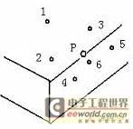
(4) Theoretical value capture After solving the import and alignment of the digital model, the capture of the theoretical value is relatively simple. For standard features such as circles, the software only needs to be able to select and identify the feature from the CAD digital model, and then the theoretical value can be directly extracted from its characteristics. For automatic measurement, it can be directly programmed according to the digital model feature to guide the machine to run to the location near the theoretical value of the feature for measurement. [page] For points on a curved workpiece, they are usually divided into surface points and edge points, and some software divides them more finely. For points on the surface, through direct measurement, the measured points are projected onto the surface along the normal of the digital model surface to obtain the theoretical points. However, edge points are different. The edge is the boundary of the CAD surface, such as the edge of a sheet metal part, and the simplest one is the edge of a cube. If you want to detect points on the edge, since the probe cannot directly and accurately measure it, and the compensation direction of the probe cannot be determined, it is impossible to measure directly, and only indirect measurement can be used. Usually, its processing principle is shown in Figure 3. In order to measure point P on the edge, points can be measured on both sides of it. In this example, the first three points are used to determine the top, the 4th and 5th points determine the boundary direction, and the last point 6 determines the position of the target point. The point generated by projecting it to the previously determined edge is considered as the edge measurement point, and its theoretical value is the closest point to the edge of the surface in the digital model.

Figure 3 Schematic diagram of edge point measurement
Through the above methods, the edge point detection can be realized. Different software may have different processing methods.
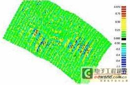
4. Current status of surface measurement software Based on 3D digital model, the detection of surface workpieces belongs to the advanced application category in three-coordinate machine measurement, and this function is generally included in high-end measurement software. At present, the more common ones in the domestic market include the CAD++ version of PC-DMIS and VIRTUL DMIS, which are developed by professional measuring machine software companies such as WILCOX and ENTELEGENCE. POWER INSPECT software is also cited in coordinate machines due to its strong function in digital model processing. It is provided by DELCAM, a British CAD/CAM software company, which also reflects the trend of closer integration of measuring machine software and CAD software. In fact, for surface quality evaluation, as part of surface construction, editing and analysis, CAD software manufacturers have had better solutions for a long time, especially in reverse engineering processing software. After processing the collected point cloud into a surface, it is often necessary to compare the deviation between the point cloud and the design curve and surface in order to improve the surface quality while ensuring accuracy. Figure 4 shows the comparative analysis of point clouds and surfaces in imageware, and the results are represented by different color gradients.

Figure 4. Example of Imagewave point cloud and surface analysis
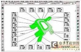
5. Research and development of ZCRMDT measurement software The research and development of measurement software in China is relatively lagging behind. For those that need advanced functions such as digital model detection, they are generally equipped with foreign software. The ZCRMDT manual version measurement software launched by the Measurement Instrument Research Institute of China Testing Technology Research Institute (China Measurement Instrument) has a complete three-dimensional graphical measurement environment, supports digital model import, dynamic simulation of probe trajectory, visual measurement, view rotation, zoom, and graphic selection, and realizes the function of using surface digital model for detection. It is worth mentioning that the digital model can also be edited and processed using the functions of the CAD platform. Figure 5 shows the use of ZCRMDT software to detect a curved surface inspection fixture. The software directly compares the measurement point on the workpiece with the digital model to obtain the deviation. The inspector adjusts the point according to the result until the deviation is within the permitted range.

Figure 5 ZCRMDT measurement example
From the technical level, ZCRMDT software, as a manual version of measurement software, has reached or is close to the level of similar foreign software, and is in an advanced position in China. At the same time, compared with foreign software, it has obvious price advantages. At present, ZCRMDT software has been equipped with manual measuring machines produced by China Measurement Instrument and has been adopted by dozens of users across the country, so that customers can achieve advanced measurement functions without spending too much money, solving customers' measurement problems.
6. Conclusion The three-coordinate surface detection technology based on 3D digital model is a highly comprehensive advanced measurement technology, involving professional disciplines such as CAD, three-coordinate measuring machine, software programming and metrology, which is by no means a simple article that can be covered. This article is a little experience of the author's experience in testing and developing related software in his work, and is specially proposed for discussion with everyone. With the development of three-coordinate measurement technology, three-coordinate measurement software will surely make more substantial progress.
Previous article:Daily maintenance and maintenance precautions of three-coordinate measuring machine
Next article:Testing high-speed clocks with low-cost instruments
- Keysight Technologies Helps Samsung Electronics Successfully Validate FiRa® 2.0 Safe Distance Measurement Test Case
- From probes to power supplies, Tektronix is leading the way in comprehensive innovation in power electronics testing
- Seizing the Opportunities in the Chinese Application Market: NI's Challenges and Answers
- Tektronix Launches Breakthrough Power Measurement Tools to Accelerate Innovation as Global Electrification Accelerates
- Not all oscilloscopes are created equal: Why ADCs and low noise floor matter
- Enable TekHSI high-speed interface function to accelerate the remote transmission of waveform data
- How to measure the quality of soft start thyristor
- How to use a multimeter to judge whether a soft starter is good or bad
- What are the advantages and disadvantages of non-contact temperature sensors?
- Innolux's intelligent steer-by-wire solution makes cars smarter and safer
- 8051 MCU - Parity Check
- How to efficiently balance the sensitivity of tactile sensing interfaces
- What should I do if the servo motor shakes? What causes the servo motor to shake quickly?
- 【Brushless Motor】Analysis of three-phase BLDC motor and sharing of two popular development boards
- Midea Industrial Technology's subsidiaries Clou Electronics and Hekang New Energy jointly appeared at the Munich Battery Energy Storage Exhibition and Solar Energy Exhibition
- Guoxin Sichen | Application of ferroelectric memory PB85RS2MC in power battery management, with a capacity of 2M
- Analysis of common faults of frequency converter
- In a head-on competition with Qualcomm, what kind of cockpit products has Intel come up with?
- Dalian Rongke's all-vanadium liquid flow battery energy storage equipment industrialization project has entered the sprint stage before production
- Allegro MicroSystems Introduces Advanced Magnetic and Inductive Position Sensing Solutions at Electronica 2024
- Car key in the left hand, liveness detection radar in the right hand, UWB is imperative for cars!
- After a decade of rapid development, domestic CIS has entered the market
- Aegis Dagger Battery + Thor EM-i Super Hybrid, Geely New Energy has thrown out two "king bombs"
- A brief discussion on functional safety - fault, error, and failure
- In the smart car 2.0 cycle, these core industry chains are facing major opportunities!
- The United States and Japan are developing new batteries. CATL faces challenges? How should China's new energy battery industry respond?
- Murata launches high-precision 6-axis inertial sensor for automobiles
- Ford patents pre-charge alarm to help save costs and respond to emergencies
- New real-time microcontroller system from Texas Instruments enables smarter processing in automotive and industrial applications
- MYC-CZU3EG core board information
- Analyzing the temperature sensor sampling circuit
- 【DFRobot motor driver】+Received DFRobot Arduino driver board
- EEWORLD University----How High-Voltage Isolation Technology Works
- New communication capabilities for TI's C2000 microcontrollers!
- At 10 am today, Keysight Technologies will broadcast a live broadcast on [Applications and Techniques of Oscilloscopes in the Electronics Industry]
- EEWORLD University ---- Live playback: Start your next-generation 4K display application design with TI DLP? technology
- The New Year is coming soon. What activities and benefits are there in the forum? Is there a year-end bonus? Haha
- [Zero Knowledge ESP8266 Tutorial] Quick Start 26 Blynk Mobile APP Displays Indoor Temperature and Humidity
- Voltage signal amplification and waveform conversion

 ICCV2023 Paper Summary: Datasets and Evaluation
 Introduction to Artificial Intelligence and Robotics (Murphy)


 京公网安备 11010802033920号