Bandwidth is the first parameter most engineers consider when choosing an oscilloscope. This article will provide you with some useful tips on how to choose the right oscilloscope bandwidth for your digital and analog applications. But first, let’s look at the definition of oscilloscope bandwidth.
Definition of Oscilloscope Bandwidth
All oscilloscopes exhibit a low-pass frequency response that rolls off at higher frequencies as shown in Figure 1. Most oscilloscopes with bandwidth specifications of 1 GHz and below typically exhibit a Gaussian response, with a slow roll-off starting at about one-third of the -3 dB frequency. Oscilloscopes with bandwidth specifications exceeding 1 GHz typically have a maximally flat frequency response, as shown in Figure 2. This frequency response typically exhibits a relatively flat response in-band, with a steeper roll-off at about the -3 dB frequency.
Each of these two frequency responses of an oscilloscope has its own advantages and disadvantages. An oscilloscope with a maximally flat frequency response will attenuate in-band signals less than an oscilloscope with a Gaussian frequency response, which means that the former will measure in-band signals more accurately. However, an oscilloscope with a Gaussian frequency response will attenuate out-of-band signals less than an oscilloscope with a maximally flat frequency response, which means that under the same bandwidth specification, an oscilloscope with a Gaussian frequency response will generally have a faster rise time. However, sometimes the greater attenuation of out-of-band signals helps to eliminate high-frequency components that may cause aliasing according to the Nyquist criterion (fMAX < fS). For a more in-depth discussion of Nyquist sampling theory, please refer to Agilent Application Note 1587.
Whether your oscilloscope has a Gaussian frequency response, a maximally flat frequency response, or something in between, we consider the lowest frequency at which the input signal is attenuated by 3 dB after passing through the oscilloscope to be the bandwidth of the oscilloscope. The bandwidth and frequency response of an oscilloscope can be measured using a sine wave signal generator sweep. The attenuation of the signal at the -3dB frequency of the oscilloscope can be converted to an amplitude error of approximately -30%. Therefore, we cannot expect to accurately measure signals whose main frequency components are close to the bandwidth of the oscilloscope.
Closely related to the oscilloscope bandwidth specification is its rise time parameter. An oscilloscope with a Gaussian frequency response, measured from the 10% to 90% standard, has a rise time of about 0.35/fBW. Oscilloscopes with a maximally flat frequency response typically have a rise time specification in the 0.4/fBW range, varying with the steepness of the oscilloscope's frequency roll-off characteristics. But we must remember that an oscilloscope's rise time is not the fastest edge speed that the oscilloscope can accurately measure, but the fastest edge speed that the oscilloscope can achieve when the input signal has a theoretically infinitely fast rise time (0 ps). Although this theoretical parameter is impossible to measure in practice because a pulse generator cannot output a pulse with an infinitely fast edge, we can measure the oscilloscope's rise time by inputting a pulse with an edge speed 3 to 5 times the oscilloscope's rise time specification.
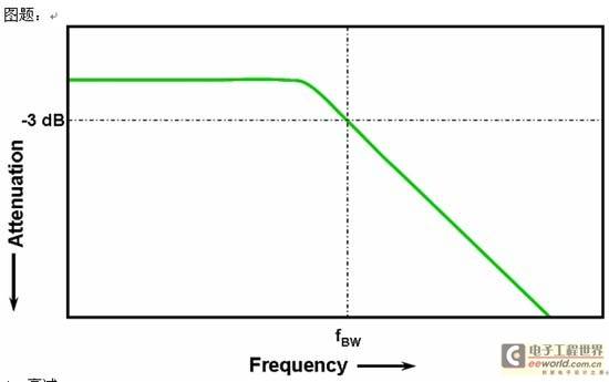
Figure 1: Low-pass frequency response
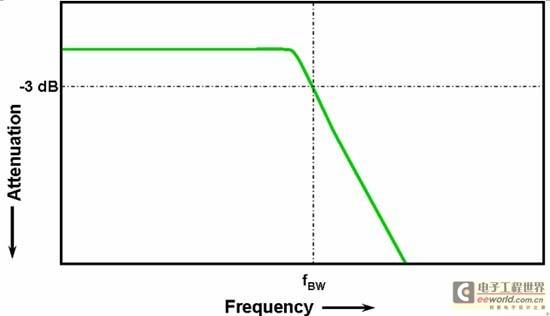
Figure 2: Maximum flat frequency response [page]
Oscilloscope bandwidth required for digital applications
A rule of thumb is that the bandwidth of an oscilloscope should be at least 5 times greater than the fastest digital clock rate of the system being measured. If the oscilloscope we choose meets this criteria, then the oscilloscope will be able to capture the 5th harmonic of the signal being measured with minimal signal attenuation. The 5th harmonic of a signal is very important in determining the overall shape of a digital signal. However, if high-speed edges need to be accurately measured, this simple formula does not take into account the actual high-frequency content contained in fast rising and falling edges.
Formula: fBW ≥ 5 x fclk
A more accurate way to determine the bandwidth of an oscilloscope is to base it on the highest frequency present in the digital signal, rather than the maximum clock rate. The highest frequency of a digital signal is determined by the fastest edge speed in the design. Therefore, we first need to determine the rise and fall times of the fastest signal in the design. This information can usually be obtained from the public data sheets of the devices used in the design.
Step 1: Determine the fastest edge speed
Then you can use a simple formula to calculate the maximum "real" frequency component of the signal. Dr. Howard W. Johnson wrote a book on this subject, High Speed Digital Design. In it, he calls this frequency component the "knee" frequency (fknee). All fast edges have an infinite number of frequency components in their spectrum, but there is a point of inflection (or "knee") above which the frequency components are insignificant in determining the shape of the signal.
Step 2: Calculate fknee
fknee = 0.5/RT (10% - 90%)
fknee = 0.4/RT (20% - 80%)
For signals with a rise time characteristic defined by a threshold of 10% to 90%, the knee frequency fknee is equal to 0.5 divided by the rise time of the signal. For signals with a rise time characteristic defined by a threshold of 20% to 80% (as is often done in device specifications today), fknee is equal to 0.4 divided by the rise time of the signal. But be careful not to confuse the signal rise time here with the rise time specification of the oscilloscope; we are talking about the actual signal edge speed here.
The third step is to determine the oscilloscope bandwidth required to measure the signal based on the accuracy required to measure the rise and fall times. Table 1 shows the relationship between the oscilloscope bandwidth required and fknee for various accuracy requirements for oscilloscopes with Gaussian or maximally flat frequency response. However, it is important to remember that most oscilloscopes with bandwidth specifications of 1 GHz and below are usually Gaussian frequency response types, while those with bandwidths above 1 GHz are usually maximally flat frequency response types.

Table 1: Factors for calculating the required bandwidth of an oscilloscope based on the accuracy required and the type of oscilloscope frequency response
Step 3: Calculate the Oscilloscope Bandwidth
Let's explain this with a simple example:
- Determine the minimum bandwidth required for an oscilloscope to have a correct Gaussian frequency response when measuring a 500ps rise time (10-90%)
- If the rise/fall time of a signal is approximately 500 ps (defined by the 10% to 90% standard), then the maximum actual frequency component of the signal (fknee) is approximately 1 GHz.
- fknee = (0.5/500ps) = 1 GHz
If a 20% timing error is allowed when measuring rise time and fall time parameters, then an oscilloscope with a bandwidth of 1 GHz will meet the requirements of this digital measurement application. However, if the timing accuracy is required to be within 3%, then an oscilloscope with a bandwidth of 2 GHz will be better.
20% Timing Accuracy:
Oscilloscope bandwidth = 1.0 x 1 GHz = 1.0 GHz
3% Timing Accuracy:
Oscilloscope bandwidth = 1.9 x 1 GHz = 1.9 GHz
Next we will use several oscilloscopes with different bandwidths to measure a digital clock signal with similar characteristics to the signal in this example.
Comparison of measurements of the same digital clock signal using oscilloscopes with different bandwidths
FIG3 shows the waveform result of measuring a 100MHz digital clock signal with an edge speed of 500ps (from 10% to 90%) using Agilent's MSO6014A oscilloscope with a bandwidth of 100MHz.
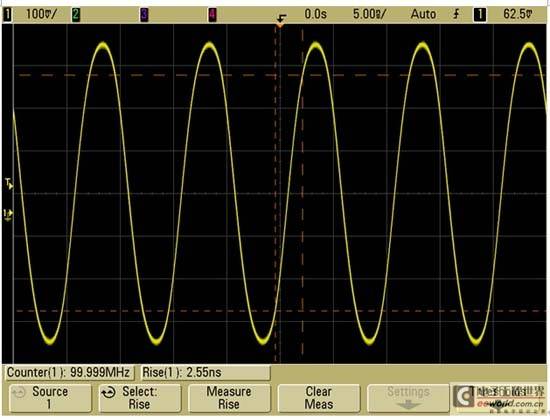
Figure 3[page]
As can be seen from the figure, the oscilloscope mainly passes only the 100MHz fundamental frequency component of the clock signal, so the clock signal appears to be approximately in the shape of a sine wave. An oscilloscope with a bandwidth of 100MHz may be very suitable for many MCU-based 8-bit designs with clock rates in the range of 10MHz to 20MHz, but it is obviously not enough for the 100MHz clock signal measured here.
Figure 4 shows the result of measuring the same signal using Agilent's 500MHz bandwidth oscilloscope MSO6054A.
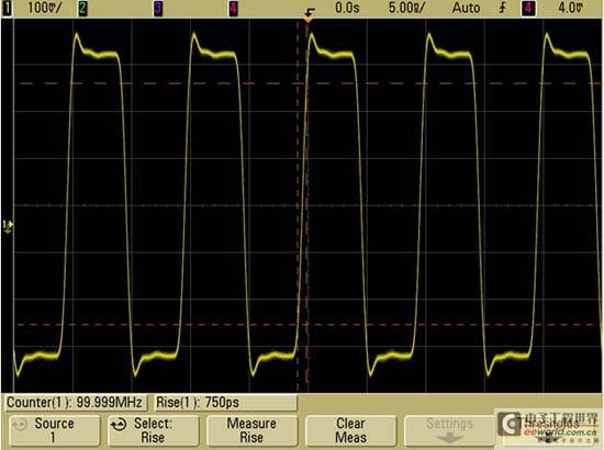
Figure 4
As can be seen from the figure, the oscilloscope can capture up to the fifth harmonic of the signal, which just meets the first empirical suggestion we gave above. However, when we measured the rise time, we found that the rise time measured by this oscilloscope was about 750ps. In this case, the oscilloscope's measurement of the signal rise time is not very accurate. The measurement result it obtains is actually very close to its own rise time (700ps), rather than the rise time of the input signal (close to 500ps). This shows that if timing measurement is more important, then we need to use an oscilloscope with a higher bandwidth to meet the requirements of this digital measurement application.
After switching to Agilent's 1-GHz bandwidth oscilloscope MSO6104A, the signal image we get (see Figure 5) is more accurate.
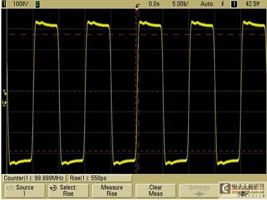
Figure 5
After selecting the rise time measurement in the oscilloscope, we get a measurement result of about 550ps. This measurement result has an accuracy of about 10%, which is very satisfactory, especially when considering the cost of the oscilloscope. However, sometimes even this measurement result obtained by a 1GHz bandwidth oscilloscope may be considered inaccurate. If we require an edge speed measurement accuracy of 3% for this signal with an edge speed of 500ps, then we need an oscilloscope with a bandwidth of 2GHz or higher, which we have already mentioned in the previous example.
After switching to an oscilloscope with a 2 GHz bandwidth, what we see now (see Figure 6) is a more accurate clock signal, with a rise time measurement of approximately 495 ps.
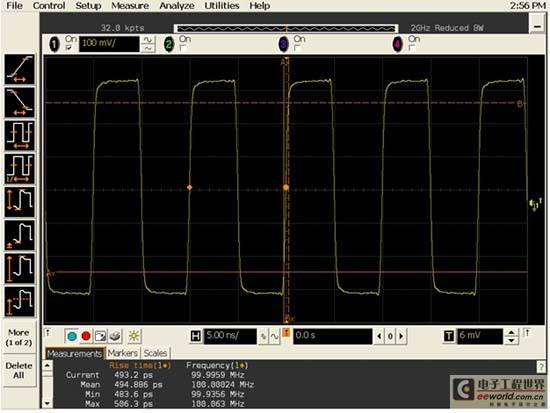
Figure 6[page]
Agilent Infiniium series high bandwidth oscilloscope has an advantage, that is, the bandwidth can be upgraded. If 2 GHz bandwidth is enough for today's application, you can just buy an entry-level 2-GHz oscilloscope at first, and then gradually upgrade it to 13 GHz when you need higher bandwidth.
Oscilloscope bandwidth required for analog applications
Many years ago, most oscilloscope manufacturers recommended that users choose an oscilloscope with a bandwidth at least three times higher than the maximum signal frequency. Although this "3X" rule does not apply to digital applications based on clock rate, it still applies to analog applications such as modulated RF signal measurements. To help readers understand the origin of this three-times multiplier, let's look at the true frequency response of a 1GHz bandwidth oscilloscope.
Figure 7 shows the swept frequency response test of Agilent's 1-GHz bandwidth oscilloscope MSO6104A (sweep frequency range 20 MHz to 2 GHz).
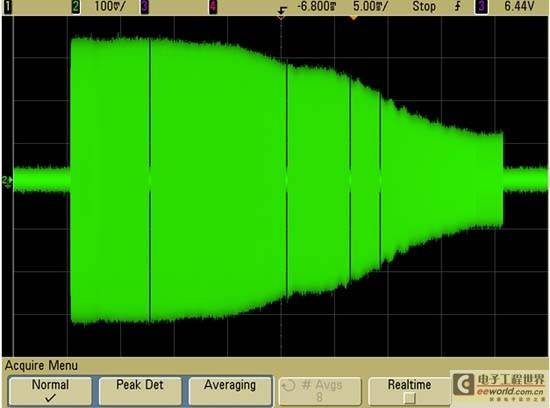
Figure 7
As can be seen from the figure, just at 1 GHz, the input signal attenuation is about 1.7 dB, which is far from exceeding the -3 dB limit that defines the oscilloscope's bandwidth. However, to accurately measure analog signals, we can only use the relatively flat part of the oscilloscope's bandwidth where the attenuation is the smallest. For this oscilloscope, at about one-third of its 1 GHz bandwidth, the input signal has basically no attenuation (attenuation is 0 dB). But not all oscilloscopes have such a frequency response.
Figure 8 shows the results of a swept frequency response test on another vendor's 1.5-GHz bandwidth oscilloscope.
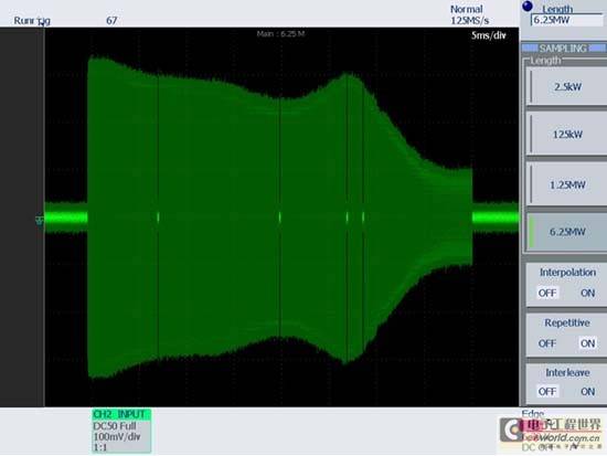
Figure 8
This is an example of a frequency response that is far from flat. The frequency response of this oscilloscope is neither Gaussian nor maximally flat. Instead, it is more like a "max-ripple" frequency response, and has severe peaking, which can cause serious waveform distortion, whether measuring analog or digital signals. Unfortunately, the bandwidth specification of the oscilloscope (the frequency at which the input signal is attenuated by 3dB) does not specify any attenuation or amplification of signals at other frequencies. On this oscilloscope, even at one-fifth of the oscilloscope's bandwidth, the signal is attenuated by about 1dB (10%). Therefore, it is unwise to select an oscilloscope based on the 3X rule in this case. Therefore, when choosing an oscilloscope, it is best to choose a product from a well-known manufacturer and pay close attention to the relative flatness of the oscilloscope's frequency response.
Conclusion
In general, for digital applications, the oscilloscope bandwidth should be at least five times faster than the fastest clock rate of the design being tested. However, when the edge speed of the signal needs to be accurately measured, the oscilloscope bandwidth should be determined based on the maximum actual frequency component of the signal.
For analog applications, the oscilloscope bandwidth should be at least three times higher than the highest frequency of the analog signal in the design under test, but this rule of thumb only applies to oscilloscopes that have a relatively flat frequency response at low frequencies.
And we can't just consider the present and ignore the future when choosing an oscilloscope. As long as the budget allows, buying an oscilloscope that is slightly better than the minimum requirements of the application today may save you a lot of investment in the future.
Previous article:How to judge the quality of high bandwidth measurement probes
Next article:Oscilloscope capturing Bode plots in non-50Ω environments
- Keysight Technologies Helps Samsung Electronics Successfully Validate FiRa® 2.0 Safe Distance Measurement Test Case
- From probes to power supplies, Tektronix is leading the way in comprehensive innovation in power electronics testing
- Seizing the Opportunities in the Chinese Application Market: NI's Challenges and Answers
- Tektronix Launches Breakthrough Power Measurement Tools to Accelerate Innovation as Global Electrification Accelerates
- Not all oscilloscopes are created equal: Why ADCs and low noise floor matter
- Enable TekHSI high-speed interface function to accelerate the remote transmission of waveform data
- How to measure the quality of soft start thyristor
- How to use a multimeter to judge whether a soft starter is good or bad
- What are the advantages and disadvantages of non-contact temperature sensors?
- Innolux's intelligent steer-by-wire solution makes cars smarter and safer
- 8051 MCU - Parity Check
- How to efficiently balance the sensitivity of tactile sensing interfaces
- What should I do if the servo motor shakes? What causes the servo motor to shake quickly?
- 【Brushless Motor】Analysis of three-phase BLDC motor and sharing of two popular development boards
- Midea Industrial Technology's subsidiaries Clou Electronics and Hekang New Energy jointly appeared at the Munich Battery Energy Storage Exhibition and Solar Energy Exhibition
- Guoxin Sichen | Application of ferroelectric memory PB85RS2MC in power battery management, with a capacity of 2M
- Analysis of common faults of frequency converter
- In a head-on competition with Qualcomm, what kind of cockpit products has Intel come up with?
- Dalian Rongke's all-vanadium liquid flow battery energy storage equipment industrialization project has entered the sprint stage before production
- Allegro MicroSystems Introduces Advanced Magnetic and Inductive Position Sensing Solutions at Electronica 2024
- Car key in the left hand, liveness detection radar in the right hand, UWB is imperative for cars!
- After a decade of rapid development, domestic CIS has entered the market
- Aegis Dagger Battery + Thor EM-i Super Hybrid, Geely New Energy has thrown out two "king bombs"
- A brief discussion on functional safety - fault, error, and failure
- In the smart car 2.0 cycle, these core industry chains are facing major opportunities!
- The United States and Japan are developing new batteries. CATL faces challenges? How should China's new energy battery industry respond?
- Murata launches high-precision 6-axis inertial sensor for automobiles
- Ford patents pre-charge alarm to help save costs and respond to emergencies
- New real-time microcontroller system from Texas Instruments enables smarter processing in automotive and industrial applications

 Signal Integrity and Power Integrity Analysis (Eric Bogatin)


 京公网安备 11010802033920号