Traditionally, the frequency response of an oscilloscope is Gaussian, and is composed of many circuit components with similar frequency responses. This is what a traditional analog oscilloscope looks like. From its BNC input to the CRT display, there are many analog amplifiers forming an amplifier chain. Note 1. The characteristics of a Gaussian frequency response oscilloscope are well known in the industry.
What is less well known is the flat frequency response commonly used in modern high-performance digital oscilloscopes. Only a few analog amplifiers in digital oscilloscopes are associated with Gaussian frequency response, and DSP technology can be used to optimize its impact on accuracy. Another important thing for digital oscilloscopes is to try to avoid sampling aliasing errors, while analog oscilloscopes do not have this problem at all. Compared with Gaussian frequency response, flat frequency response can reduce sampling aliasing errors. Here we first review the characteristics of Gaussian response and flat response. Then we discuss the rise time measurement accuracy corresponding to these two response types. This shows that an oscilloscope with a flat frequency response has a higher rise time measurement accuracy than a Gaussian response oscilloscope with the same bandwidth.
Our discussion takes a 1 GHz oscilloscope as an example. The analysis conclusions here are fully applicable to other bandwidths.
Characteristics of Gaussian Response Oscilloscopes
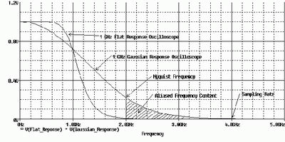
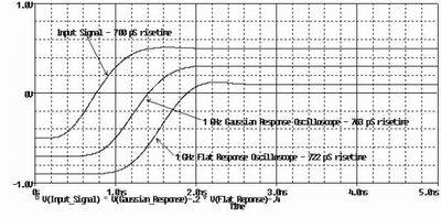
The typical Gaussian frequency response of a 1GHz oscilloscope is shown in Figure 1. The advantage of a Gaussian frequency response is that no matter how fast the input signal (the measured signal) is, it can give a good pulse response without overshoot (that is, the signal displayed on the oscilloscope screen has no overshoot). Figure 2 shows the pulse response of a 1GHz Gaussian frequency response oscilloscope to a fast-edge step signal.
In a Gaussian frequency response oscilloscope, there is a well-known common formula between the oscilloscope's rise time Note 3 and the oscilloscope's bandwidth Note 4:
Rise time = 0.35 / bandwidth Note 5 (Gaussian system)
Another commonly used characteristic of a Gaussian system is its total system bandwidth. Note 6 This is the RMS value of the bandwidths of the individual subsystems and can be calculated using the familiar relationship:
![]()
Typically, if the oscilloscope probe bandwidth is higher than the oscilloscope bandwidth, the system bandwidth will not be significantly worse.
Instead, the measured rise time is usually related to the system and signal rise time, calculated as:
![]()
When the rise time of the oscilloscope system is not much faster than the signal rise time, this relationship can be used to estimate the actual rise time of the signal.

Figure 1[page]
Figure 1 compares a flat response to a Gaussian response. Note that it has a much flatter frequency response before -3dB, but then falls off rapidly after -3dB. This response shape is sometimes referred to as a maximally flat response or a brick wall response.
Flat response has two major advantages. The first advantage is that the frequency response of the signal before the -3dB bandwidth is relatively flat, that is, the attenuation is small, and the measurement result is more accurate. The second advantage is that after exceeding the -3dB bandwidth, the frequency response curve rolls off sharply, greatly reducing the chance of sampling aliasing in the digital oscilloscope (more details later).
In the time domain, when there is a fast-edge step signal input, a flat frequency response oscilloscope will produce pulse overshoot and ringing, as shown in Figure 2. We know that overshoot and ringing are bad responses of oscilloscopes. However, this situation will only occur when the signal rise time is very fast, far exceeding the ability of the oscilloscope to accurately measure. In this case, a higher bandwidth oscilloscope should be used, otherwise the measurement error will be large.

Figure 2
Unlike Gaussian systems, the system bandwidth of a flat frequency response oscilloscope cannot be determined by the RMS values of its subsystem components. The bandwidth and rise time formulas used for Gaussian response oscilloscope systems do not apply to flat response oscilloscope systems! Instead, the oscilloscope manufacturer needs to provide the oscilloscope system bandwidth, which is the combined bandwidth of the oscilloscope/probe and its front-end accessories.
In the case of a flat response oscilloscope, rise time is related to bandwidth by:
Rise time = N / bandwidth (here N = 0.4 to 0.5)
The larger the N, the steeper the frequency response, or the more "brick-wall" it is. The above relationship is sometimes included in oscilloscope specifications to give the type of response the oscilloscope has.
Measurement accuracy
Which frequency response type provides the best measurement accuracy? The maximum signal frequency and the oscilloscope's sampling aliasing error need to be considered.
Signal maximum frequency
In the example of Figure 1, the flat frequency response has less attenuation before the -3dB bandwidth (1GHz) than the Gaussian response. Therefore, for the signal frequency components within the -3dB bandwidth, the measurement accuracy of the flat response oscilloscope is much higher than that of the Gaussian response oscilloscope.
For example, let's compare the measurement results of a signal with a rise time of 700ps using these two types of frequency response oscilloscopes. The highest frequency of the signal can be determined from the rise time, which is:
Signal maximum frequency = 0.5 / rise time
The definition of the highest frequency of a signal is: the highest frequency (including the frequency components within the highest frequency) that any measurement system (including oscilloscopes) can accurately reproduce the signal. Note 8.
Using this relationship, we can get a signal with a rise time of 700ps, with a major frequency below 714MHz. We can see from Figure 1 that for frequencies up to 714MHz, the flat response oscilloscope has less attenuation than the Gaussian response oscilloscope, and can more accurately measure the rise time of the 700ps transition edge, as shown in Figure 3. The flat frequency response oscilloscope measures this rise time with an error of 3%, while the Gaussian frequency response oscilloscope measures this rise time with an error of 9%.

Figure 3[page]
If the rise time of the measured signal is particularly fast (i.e., faster transition edges), the Gaussian response oscilloscope will eventually exceed the rise time measurement accuracy of the flat response oscilloscope. This is because as the signal rise time decreases (i.e., faster transition edges), the frequency components above -3dB increase, and the amplitude response of the flat response oscilloscope will be lower than that of the Gaussian response oscilloscope.

Figure 4
Figure 4 shows the measurement error of the two oscilloscopes used in our example for signals with different rise times. Note that at the border where the Gaussian response oscilloscope's measurement accuracy exceeds that of the flat response oscilloscope, the rise time measurement error has reached 15%. Therefore, for accurate (< 15%) measurement of signal rise time, the flat response oscilloscope is far superior to the Gaussian response oscilloscope at the same bandwidth. This is inconsistent with the common intuition that for an ideal (fast) step signal input, a Gaussian response oscilloscope will have a faster rise time than a flat response oscilloscope. It is important to remember that the oscilloscope rise time specification alone does not fully indicate how accurate the measured rise time is, and the frequency response type of the oscilloscope must also be considered.
Sampling aliasing error
Digital oscilloscopes use two basic sampling methods: repetitive sampling and real-time sampling. Repetitive sampling oscilloscopes are used for repetitive signals. They construct a waveform from multiple acquired samples, which is less prone to sampling aliasing errors. Real-time sampling oscilloscopes often capture all signal information at once, or once there is a signal you are interested in, they acquire it, otherwise they wait. The discussion here focuses on the more common real-time sampling oscilloscope, which has more advantages than repetitive sampling oscilloscopes.
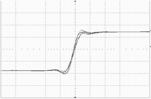
For a digital real-time oscilloscope to accurately measure a signal, the signal must not have too many frequency components above the NyQuist frequency, which is equal to half the sampling frequency. In the frequency domain, frequency components above the NyQuist frequency will be folded to below the NyQuist frequency. In the time domain, this error appears as an impulse response with "jittering" transition edges, as shown in Figure 5. "Jittering" transition edges will result in inconsistent rise time and time difference measurements.

Figure 5
For the example in Figure 1 with a sampling rate of 4 GHz Note 9, the NyQuist frequency is 2 GHz. A Gaussian response oscilloscope allows sampling of frequency components above 2 GHz, which can cause sampling aliasing errors to the signal. However, a flat response oscilloscope attenuates all frequency components above 2 GHz, so there is no sampling aliasing error. [page]
To accurately measure the signal without sampling aliasing errors, the oscilloscope must have a sufficient sampling rate. For a Gaussian response oscilloscope, the sampling rate usually needs to be 4 times the oscilloscope bandwidth, or even 6 times the oscilloscope bandwidth. A flat response oscilloscope has a steep filter, so a sampling rate of 2.5 times the oscilloscope bandwidth can avoid aliasing errors.
Determine how much bandwidth you need
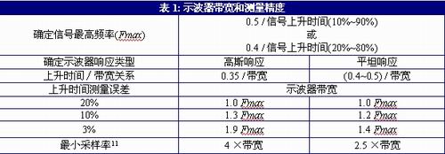
To estimate the oscilloscope bandwidth required for accurate measurements, refer to the information provided in Table 1. The first step is to determine the highest signal frequency (Fmax) based on the signal rise time Note 10. Then, multiply the highest signal frequency (Fmax) by an appropriate factor based on the required measurement accuracy to determine the required oscilloscope bandwidth. The last step is to ensure that the oscilloscope has sufficient sampling rate to achieve the required bandwidth without sampling aliasing errors.

For example, to measure a signal with a rise time of 100ps (20% to 80%) with a flat response oscilloscope with an accuracy of 10%, the required bandwidth is (0.4 / 100ps) × 1.2 = 4.8GHz, and the minimum sampling rate is 4.8GHz × 2.5 = 12GSa/s. If the measurement accuracy requirement is 3%, the required bandwidth is (0.4 / 100ps) × 1.4 = 5.6GHz, and the minimum sampling rate is 5.6GHz × 2.5 = 14GSa/s.
This method is only intended to estimate the required bandwidth. Various oscilloscopes have different frequency responses, and the actual accuracy of the rise time must be carefully verified by measurement.
Summarize
For accurate measurement of digital signal rise time (error < 15%), a flat response oscilloscope has better measurement accuracy than a Gaussian response oscilloscope of the same bandwidth. Another benefit of a flat response oscilloscope is that it usually has a brick wall filter to reduce or prevent sampling aliasing errors.
The bandwidth of the oscilloscope required is determined primarily by the rise time of the signal, not by the signal frequency. To make accurate measurements, the frequency response of the selected oscilloscope should cover the highest frequency of the measured signal (determined by the formula 0.5/rise time (10% ~ 90%)). For modern flat response oscilloscopes, accurate rise time measurements can generally be made as long as the oscilloscope bandwidth reaches 1.4 times the highest signal frequency.
About the Author:
Dennis Weller graduated from California Institute of Technology with a bachelor's and master's degree. Dennis has been with Agilent Technologies/HP for 22 years and has been engaged in oscilloscope design. Currently, he is a technical planning expert. In his spare time, Dennis likes outdoor sports.
Note 1: The measured rise time refers to the time from the pulse 10% amplitude point to the 90% amplitude point.
Note 2: Bandwidth is defined as the frequency corresponding to the -3dB attenuation of the frequency response (the input is a single-frequency sine wave signal).
Note 3: The theoretical relationship for a Gaussian system is: rise time = 0.339/bandwidth, but the industry generally uses a practical formula of 0.35/bandwidth.
Note 4: System bandwidth refers to the bandwidth achieved by the combination of the oscilloscope probe, its front-end accessories and the oscilloscope.
Note 5: This statement implies that the oscilloscope should have a linear phase response within its passband.
注6:Johnson, Howard 和 Martin Graham, High-Speed Digital Design: A Handbook of Black Magic, page 2, Prentice Hall, 1993
Note 7: The sampling rate of a digital oscilloscope should generally be four times the specified real-time bandwidth.
Note 8: Different applications have different bandwidth requirements. Higher bandwidth may help capture noise and jitter that exceeds the highest signal frequency.
Note 9: The sampling rate of a digital oscilloscope should generally be four times the specified real-time bandwidth.
Note 10: Different applications have different bandwidth requirements. Higher bandwidth may help capture noise and jitter above the highest signal frequency.
11: Typical value. Different models of oscilloscopes have different values. Please refer to the technical specifications of the oscilloscope.
Previous article:Preventing current probe damage and instructions for using current probes
Next article:Application of digital oscilloscope in high frequency signal acquisition
- Keysight Technologies Helps Samsung Electronics Successfully Validate FiRa® 2.0 Safe Distance Measurement Test Case
- From probes to power supplies, Tektronix is leading the way in comprehensive innovation in power electronics testing
- Seizing the Opportunities in the Chinese Application Market: NI's Challenges and Answers
- Tektronix Launches Breakthrough Power Measurement Tools to Accelerate Innovation as Global Electrification Accelerates
- Not all oscilloscopes are created equal: Why ADCs and low noise floor matter
- Enable TekHSI high-speed interface function to accelerate the remote transmission of waveform data
- How to measure the quality of soft start thyristor
- How to use a multimeter to judge whether a soft starter is good or bad
- What are the advantages and disadvantages of non-contact temperature sensors?
- Innolux's intelligent steer-by-wire solution makes cars smarter and safer
- 8051 MCU - Parity Check
- How to efficiently balance the sensitivity of tactile sensing interfaces
- What should I do if the servo motor shakes? What causes the servo motor to shake quickly?
- 【Brushless Motor】Analysis of three-phase BLDC motor and sharing of two popular development boards
- Midea Industrial Technology's subsidiaries Clou Electronics and Hekang New Energy jointly appeared at the Munich Battery Energy Storage Exhibition and Solar Energy Exhibition
- Guoxin Sichen | Application of ferroelectric memory PB85RS2MC in power battery management, with a capacity of 2M
- Analysis of common faults of frequency converter
- In a head-on competition with Qualcomm, what kind of cockpit products has Intel come up with?
- Dalian Rongke's all-vanadium liquid flow battery energy storage equipment industrialization project has entered the sprint stage before production
- Allegro MicroSystems Introduces Advanced Magnetic and Inductive Position Sensing Solutions at Electronica 2024
- Car key in the left hand, liveness detection radar in the right hand, UWB is imperative for cars!
- After a decade of rapid development, domestic CIS has entered the market
- Aegis Dagger Battery + Thor EM-i Super Hybrid, Geely New Energy has thrown out two "king bombs"
- A brief discussion on functional safety - fault, error, and failure
- In the smart car 2.0 cycle, these core industry chains are facing major opportunities!
- The United States and Japan are developing new batteries. CATL faces challenges? How should China's new energy battery industry respond?
- Murata launches high-precision 6-axis inertial sensor for automobiles
- Ford patents pre-charge alarm to help save costs and respond to emergencies
- New real-time microcontroller system from Texas Instruments enables smarter processing in automotive and industrial applications
- How is the storage period of components calculated?
- Let me show you how to calculate a current transformer!
- UHF Duplexer
- How to assign initial values to a continuous RAM range in C2000 chip
- Urgently hiring Linux driver engineer + six insurances and one fund + talent apartment + work residence permit
- Theory and Implementation of Narrow-Band IF Sampling Based on DSP_C54X
- [TI recommended course] #Boost and buck-boost DCDC converters help wireless charging design#
- The microcontroller has its own EEPROM. Is it necessary to add an external EEPROM? Small-volume and high-capacity EEPROMs are more expensive!
- I am facing a problem during the debian burning process of the Sipeed LicheeRV 86 development board?
- FIFO problem of vivado2018.1

 Signal Integrity and Power Integrity Analysis (Eric Bogatin)


 京公网安备 11010802033920号