In medium and high voltage switchgear, the temperature rises due to oxidation corrosion of copper bars and loose bolts. If not maintained in time, it will cause major safety accidents. Let's take a look at the scene.
With the continuous increase in electricity demand, people are paying more and more attention to electricity safety. The temperature measurement of medium and high voltage switch cabinets has always been the focus of people's attention. As the wireless zigbee technology becomes more and more popular, this solution has solved the problem of copper busbar temperature monitoring in medium and high voltage switch cabinets. However, this solution also has defects. How to achieve low power consumption, small size and rapid development has always restricted the application of wireless temperature measurement. The copper busbar in the switch cabinet is compactly arranged and there is no large free space. It is generally installed in the form of a strap. This method requires the temperature acquisition module to be very small. Since it is inconvenient to take electricity on site, batteries are mostly used for power supply. The service life of the entire temperature acquisition module is at least 3 years. In order to ensure insulation safety, glue is used to seal it, which makes it inconvenient to replace the battery. Generally, wireless temperature acquisition mostly adopts: MCU+zigbee+temperature sensor. This solution is large in size, high in power consumption, and cumbersome to develop. Here is a more convenient and practical solution for everyone.
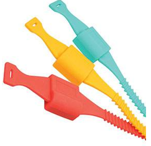
Figure 1 Wireless temperature collection strap
1. Zigbee + temperature sensor integrated solution
In order to reduce power consumption and control volume, no additional MCU can be added, and all acquisition control must be completed in the zigbee module. In order to prevent the entire system from consuming power when the zigbee module is dormant, the temperature sensor DS18B20 is set to single-line communication mode. When the zigbee module wakes up for acquisition, zigbee communicates with the temperature acquisition module and charges the capacitor in the temperature sensor DS18B20 at the same time. Users can set the sleep wake-up time through the host computer software, which can be set in seconds or minutes. After configuration, the module is scheduled to sleep. When the module wakes up, the temperature acquisition is transmitted to the master node through the zigbee network, and it enters sleep again after the transmission is completed. This solution not only has low power consumption and small size, but also greatly shortens the user's R&D cycle. Users only need to focus on the development of their own master node, and the slave node only needs to be configured.

Figure 2 Temperature acquisition block diagram
The ZigBee module and battery are integrated into a watch strap, which is then tied to the copper plate under test. There are holes on the back of the watch strap to facilitate contact between the temperature sensor and the copper plate under test.
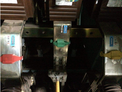
Figure 3 On-site installation pictures
The entire network adopts a star network topology. The intelligent control switch in the switch cabinet is the main node, and the temperature collection strap is the sub-node. The sub-node regularly uploads the collected temperature and then sleeps again. The main nodes are connected through the RS-485 network, and then transmitted to the monitoring background through GPRS DTU.

Figure 4 Block diagram of wireless temperature measurement system
2. Core components: zigbee module introduction
Ultra-small size
This solution uses the low-power, small-volume Nano Zigbee module developed by Guangzhou Zhiyuan. As shown in the figure below, the Zigbee module generally uses a ceramic antenna. The low-power module can be as small as 13.5mm*16.5mm, which is just right for a standard watch strap. If it is larger, it will be a bit difficult to put it in. The height of the entire module is just right with the stamp hole method. If the pin header method is used, the height will be too high when the thickness of the base plate is taken into account.
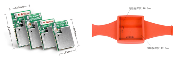
Figure 5 Zigbee module size
Excessive power consumption
The module not only has an ultra-small size but also has ultra-low power consumption. As shown in the table below, the low-power module sends only 20mA of current, and only 160nA in sleep mode. Theoretically, it can work for 5-6 years if it wakes up once every 2 minutes.

Figure 6 Zigbee module power consumption
The following figure is a comparison of power consumption of similar products
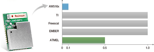
Figure 7 Power consumption comparison
3.6V power supply, no other power module required
Commonly used ER14250H batteries are all powered by 3.6V. ZLG Zhiyuan Electronics' Nano modules support 3.6V power supply and do not require other devices, thus avoiding increased power consumption and volume.
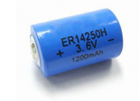
Figure 8 Battery
Supports host computer software configuration, fast product development
The Nano module supports host computer software configuration, which can set the master node ID and sleep acquisition time to achieve zero-code control.
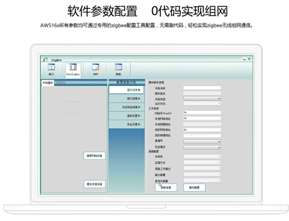
Figure 9 Host computer software configuration
3. Temperature Sensor Introduction
This solution uses DS18B20 as the temperature sensor. The sensor is small in size and easy to install. It can use single-line communication and does not require an additional power interface. When the Zigbee module is in sleep mode, the DS18B20 is in the off state.
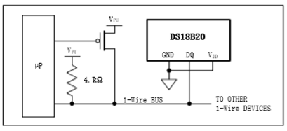
Figure 10 Single-line power supply
Previous article:Application of infrared temperature sensor in non-contact ear thermometer
Next article:ams temperature sensors help cold storage equipment designers meet stringent tolerance targets
- Melexis launches ultra-low power automotive contactless micro-power switch chip
- Infineon's PASCO2V15 XENSIV PAS CO2 5V Sensor Now Available at Mouser for Accurate CO2 Level Measurement
- Milestone! SmartSens CMOS image sensor chip shipments exceed 100 million units in a single month!
- Taishi Micro released the ultra-high integration automotive touch chip TCAE10
- The first of its kind in the world: a high-spectral real-time imaging device with 100 channels and 1 million pixels independently developed by Chinese scientists
- Melexis Launches Breakthrough Arcminaxis™ Position Sensing Technology and Products for Robotic Joints
- ams and OSRAM held a roundtable forum at the China Development Center: Close to local customer needs, leading the new direction of the intelligent era
- Optimizing Vision System Power Consumption Using Wake-on-Motion
- Infineon Technologies Expands Leading REAL3™ Time-of-Flight Portfolio with New Automotive-Qualified Laser Driver IC
- Innolux's intelligent steer-by-wire solution makes cars smarter and safer
- 8051 MCU - Parity Check
- How to efficiently balance the sensitivity of tactile sensing interfaces
- What should I do if the servo motor shakes? What causes the servo motor to shake quickly?
- 【Brushless Motor】Analysis of three-phase BLDC motor and sharing of two popular development boards
- Midea Industrial Technology's subsidiaries Clou Electronics and Hekang New Energy jointly appeared at the Munich Battery Energy Storage Exhibition and Solar Energy Exhibition
- Guoxin Sichen | Application of ferroelectric memory PB85RS2MC in power battery management, with a capacity of 2M
- Analysis of common faults of frequency converter
- In a head-on competition with Qualcomm, what kind of cockpit products has Intel come up with?
- Dalian Rongke's all-vanadium liquid flow battery energy storage equipment industrialization project has entered the sprint stage before production
- Allegro MicroSystems Introduces Advanced Magnetic and Inductive Position Sensing Solutions at Electronica 2024
- Car key in the left hand, liveness detection radar in the right hand, UWB is imperative for cars!
- After a decade of rapid development, domestic CIS has entered the market
- Aegis Dagger Battery + Thor EM-i Super Hybrid, Geely New Energy has thrown out two "king bombs"
- A brief discussion on functional safety - fault, error, and failure
- In the smart car 2.0 cycle, these core industry chains are facing major opportunities!
- The United States and Japan are developing new batteries. CATL faces challenges? How should China's new energy battery industry respond?
- Murata launches high-precision 6-axis inertial sensor for automobiles
- Ford patents pre-charge alarm to help save costs and respond to emergencies
- New real-time microcontroller system from Texas Instruments enables smarter processing in automotive and industrial applications
- Please tell me what does it mean to subscribe to OBJECT resources in the China Mobile IoT ONENET platform?
- Low power design technology overview.doc
- 【AT32WB415 Review】RTC Electronic Clock
- Can anyone recommend a DCDC module with an isolation strength of more than 6000VAC?
- Design a circuit for corridor voice-controlled lights that includes a single-chip microcomputer.
- Getting Started with the ST SensorTile.box Sensor Kit (2) Getting Started Mode Experience
- FAQ_How to implement low power mode and low power wake-up function in 24G private protocol applications
- [Rawpixel RVB2601 development board trial experience] 4. General hardware timer test
- Ask a question about Verilog
- Share MODBUS examples based on MSP430

 Wireless sensor networks controlled by multiple buses
 Research on Ultrasonic Collision Avoidance Warning System


 京公网安备 11010802033920号