Experiment and analysis of several micro motor drive circuits
Source: InternetPublisher:拿铁三分糖 Keywords: Motor drive circuit Updated: 2024/10/08
The following circuit is used to drive a 3V powered micro DC motor. This motor has two leads. By changing the polarity of the two leads, the motor can be reversed. The drive circuit is required to be able to perform forward and reverse rotation and stop control.
Circuit 1
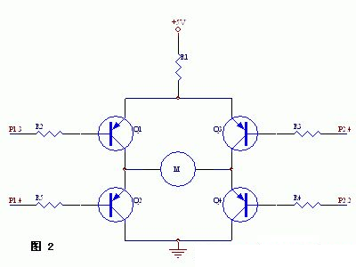
As shown in the figure below, this circuit is the original design of the author. P1.3, P2.2 and P2.4 are the IO pins of the 51 single-chip microcomputer respectively. The working principle of the design is: when P1.3 is high and P2.2 and P2.4 are both low, the motor rotates forward. At this time, Q1 and Q4 are turned on, Q2 and Q3 are turned off, and the current injection direction is +5V à R1 à Q1 à M à Q4; when P1.3 is low and P2.2 and P2.4 are both high, the motor reverses. At this time, Q2 and Q3 are turned on, Q1 and Q4 are turned off. When P2.2 is high and P2.4 is low, the circuit is completely blocked and the motor stops.
Resistors in the figure: R1 = 20Ω, R2 = R3 = R4 = 510Ω

But the actual experimental situation is unexpected, that is, the motor does not rotate in the forward and reverse directions. After measurement, when P1.3 is high, P2.2 and P2.4 are both low, Q4 is turned on, but Q1 is not turned on, and the level of P1.3 is only about 0.67V, so Q1 cannot be turned on.
The reasons are as follows: The P1, P2, and P3 pins of 51 are pulled up by resistors internally, and connected to the ground by MOSFET tubes. The so-called high level means that the MOSFET is cut off, and the pin pull-up resistor pulls it to a high level. If the internal pull-up resistor is very large, such as 20K, then when the circuit in the figure above is connected, the maximum current flowing through the b pole of Q1 is (5-0.7)/20mA=0.22mA, which makes it difficult to turn on Q1. So this circuit is not connected.
Summary: The pin pull-up capability of the 51 microcontroller is weak and is not enough to drive the transistor to turn on.
Circuit 2
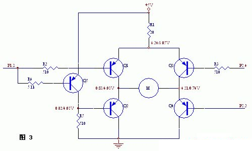
As shown in the figure below: In this circuit, all four transistors are PNP type. In this way, the drive for conduction is to control the pin to output a low level, and when 51 is at a low level, it is grounded through the MOSFET, so the pull-down capability is extremely strong.
However, Q1 and Q3 of this circuit need to be controlled separately, and more control pins are required. If you want to use one IO pin to control, you can add an inverter. However, Q1 and Q3 of this circuit need to be controlled separately, and more control pins are required. If you want to use one IO pin to control, you can add an inverter. As shown in Figure 3. The measured voltage values of each point are marked in the figure.


Circuit Three
In circuit 2, since the emitters of Q2 and Q4 are 0.7V higher than the base, and the base is at least 0V, there is actually a MOSFET voltage drop inside the CPU pin, so the emitters of Q2 and Q4 will not be lower than 1V, which reduces the effective voltage range across M.
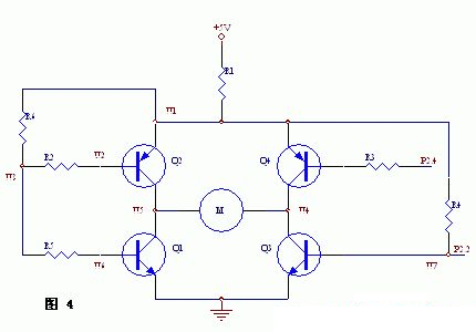
To solve this problem, Q2 and Q4 need to be replaced with NPN tubes. However, the drive of NPN tubes is shown in Circuit 1. It is not enough to rely on the pull-up of CPU pins alone, so a pull-up resistor is required, as shown in the figure below.

In the figure above, the difference from circuit 1 is that the two NPN tubes are moved to the bottom and the PNP is at the top, so that the collector potential of Q1 and Q3 can reach a tube voltage drop (0.3V) at the lowest. This increases the voltage drop range of M.
But in order to ensure sufficient drive for the NPN tube, pull-up resistors must be added to P1.3 and P2.2, as shown in the figure. In the figure, R2, R5, and R6 are indispensable. Therefore, the number of components used in this circuit is relatively large.
Also, R5 should be several times larger than R6, such as 10 times, so that when Q1 is turned on, the voltage at P1.3 can be larger and will not turn on Q2. If R5 is too small or 0, when Q1 is turned on, the voltage drop at P1.3 is only about 0.7V, which will turn on Q2 as well.
After testing, R2, R6, R3, and R4 can be set to 510Ω, and R5 to 5.1kΩ. Under this value, the voltages at various locations are as follows (R1 is 20 ohms):
U1: 4.04 U2: 2.99 U3: 3.87 U4: 4.00 U5: 0.06 U7: 0.79
Circuit Four
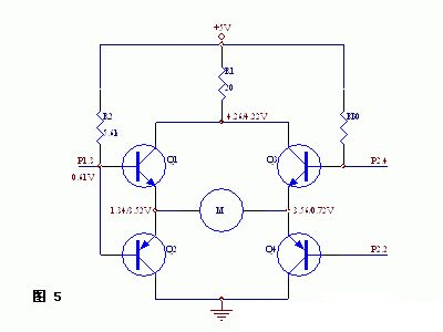
This circuit is modified from Circuit 1, as shown in Figure 5, where the measured voltage values at each point are marked:
In this figure, the base current limiting resistors are removed because the circuit designed by the author requires fewer components. From the circuit analysis, it doesn't matter, R1 plays the role of overall current limiting, and there is a pull-up resistor inside the pin, which ensures that the circuit will not pass too much current.
This circuit allows the motor to run.
However, the selection of R2 is very important, because the pull-up effect of R2 not only affects Q1, but also affects the conduction of Q2. If R2 is too small, although it is beneficial to the conduction of Q1, it will resist the conduction of Q2, because the smaller R2 is, the stronger the pull-up effect is, and the conduction of Q2 requires the lower the potential of P1.3, the better, so this is contradictory. In other words, the conduction conditions of Q1 and Q2 are contradictory.
Through experiments, 5.1k ohms is more suitable for R2. It can be seen that although this circuit saves components and CPU pins, the driving ability has a maximum limit, that is, under the mutual constraints of the driving of Q1 and Q2, only a compromise solution can be taken that is similar to both. Otherwise, if one amplification factor is large, the other will become smaller.
Summary: The above circuits have their own advantages and disadvantages, and should be selected according to the application.
- Peripheral circuit of automotive motor controller power supply chip
- How to Build a Gesture-Controlled Elevator Prototype Using Arduino Nano
- Manual automatic air compressor control circuit
- Design and principle analysis of practical electric curtain remote control device
- Temperature control circuit design and analysis
- Simple three-phase motor phase loss protection circuit
- Motorcycle anti-theft device circuit design
- Ultra-short wave item left behind reminder alarm
- Night dog barking anti-theft reminder circuit
- Rolling door anti-theft device
- Pyroelectric automatic door control circuit
- fire smoke control circuit
- Ringtone control circuit
- Car window control circuit
- Microwave oven control circuit
- Traffic traffic light control circuit
- Photoelectric output control circuit
- Forward and reverse control circuit of micro DC motor b
- Micro DC motor steady speed control circuit b
- 35W half-wave resistor-capacitor phase-shift trigger actuation control circuit


 京公网安备 11010802033920号