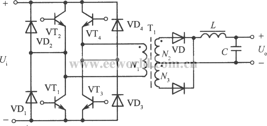
Full bridge power conversion circuit
Source: InternetPublisher:明天见 Updated: 2012/05/05
A full-bridge converter circuit can be formed by replacing the two electrolytic capacitors in the half-bridge converter circuit with two other high back-voltage power transistors and matching them with appropriate drive circuits, as shown in the figure. VTl, VT2, VT3, and VT4 form four bridge arms. High frequency transformer T is connected between them. VTl, VT4 and VT2, VT3 on the opposite arm are excited by the drive circuit and turned on alternately, converting the DC input voltage into a high-frequency square wave AC voltage. Its working process is the same as that of push-pull power conversion circuit. In this way, when the high-frequency transformer is working, the voltage obtained by its primary coil is the power supply voltage. It is twice the output voltage of the half-bridge circuit, and the withstand voltage of each transistor is still the power supply voltage, doubling the output power. If the current reaches the level of the half-bridge circuit, that is, if the current is doubled, the output power can be increased by 4 times.
 The main disadvantage of the full-bridge circuit is that it requires four sets of transistor base drive circuits that are insulated from each other, which increases the cost and complexity of the control drive circuit.
 The main disadvantage of the full-bridge circuit is that it requires four sets of transistor base drive circuits that are insulated from each other, which increases the cost and complexity of the control drive circuit.
 Latest Power Circuits Circuits
- How much current can a 2N3055 solar cell produce? How can I get 3055V from a 12N2 solar cell?
- Energy-saving motorcycle rectifier regulator
- Simple and practical LED lamp driving circuit
- Low cost and high performance LED constant current power supply
- Dual forward converter schematic diagram
- An ultra-low output voltage regulator
- Power supply circuit that can reduce LM317 ripple
- 0.7~24V continuously adjustable current limiting power supply
- Production of backup power supply for cordless phone
- Car Audio Power Supply
Popular Circuits
- DC 12V to AC 100V inverter power supply circuit design
- Power circuit a composed of intelligent thyristor modules
- EPSON PHOTO 830U printer power circuit
- 2-phase CPU power supply circuit using HIP6302 and HIP6602 chips
- KGDS type single-phase low temperature iron plated power supply circuit
- 500A-6V single-phase thyristor voltage regulating electroplating power supply circuit
- Simple dual-channel variable DC power supply circuit
- Timing switch AC power circuit
- Low voltage adjustable reference power circuit
- Household emergency power circuit 02


 京公网安备 11010802033920号