0.7~24V continuously adjustable current limiting power supply
Source: InternetPublisher:天天都吃好吃的 Keywords: Current Limitation Power Transformer Updated: 2024/08/15
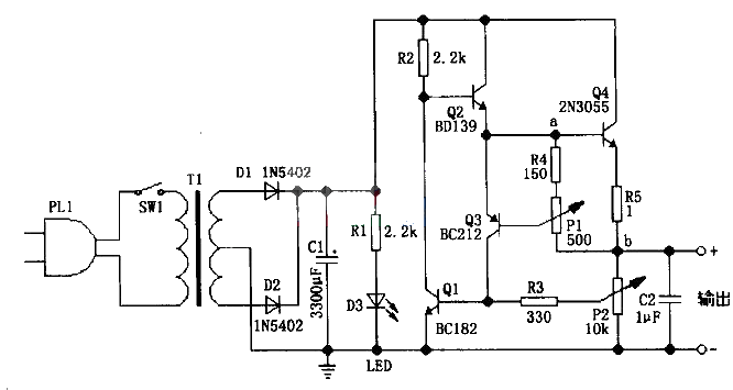
The circuit in the figure can achieve a continuously adjustable output voltage of 0.7 to 24V, and can achieve an adjustable maximum output current limit of 50mA to 2A.
P1 is used to set the maximum limit of output current. Adjusting it can give a current limit of 50mA to 2A at the corresponding output voltage. The principle of P1 setting the maximum limit of output current is as follows: As can be seen from the figure, the output current mainly comes from the emitter of Q4. In this way, when the output current increases, the voltage between points a and b in the circuit also increases. At this time, the voltage between point a (i.e., the e pole of Q3) and the b pole of Q3 also increases, and the voltage between the e and b poles of Q3 cannot exceed 0.7V. When the voltage between the e and b poles of Q3 increases, the e pole of Q3 will divert the current flowing to the b pole of Q4. In this way, the increase of the voltage between points a and b is limited, thereby achieving the purpose of limiting the maximum output current.
P2 is used for output voltage regulation. When the output voltage increases, the voltage between the e and b poles of Q1 also increases, which causes Q1 to shunt the current flowing to the b pole of Q2. After the conduction current of Q2 decreases, it is not difficult to see that the conduction current of Q4 also decreases, thereby reducing the output voltage. When the output voltage decreases, the principle is similar.
P2 recommends using a logarithmic potentiometer, so that the output voltage will be more adjustable and linear.
The output voltage and capacity of the power transformer should be selected according to the output voltage and current you need. The best solution is: the transformer secondary voltage is 36, 40, 48V or 50, 75, 80V with a center tap, and the capacity is 100VA.
Capacitor C1 can be selected from 2200~6800uF/35~50V.
In the circuit, BC182 is a 50V/100mA/NPN transistor, BD139 is an 80V/1.5A/NPN transistor, BC212 is a 50v/100mA/PNP transistor, and 2N3055 is a 60V/15A/NPN transistor. Q4 must use a heat sink, and it can be replaced by TIP3055.

- How to use a simple circuit to achieve a smooth soft-start for an isolated converter
- BA6104 five-digit LED level meter driver integrated circuit basic application circuit
- Switching power supply circuit composition and function introduction of each part
- Dual forward converter schematic diagram
- Boost drive circuit composed of RT8450
- Dynamic power supply for power amplifier controlled by thyristor
- Design of electric vehicle charger
- MAX1811 Lithium Battery Charger Production
- Detailed explanation of mobile phone charger circuit diagram
- Homemade home inverter circuit diagram
- Power circuit of LBO-522 dual trace oscilloscope
- 2-phase CPU power circuit using HIP6302 and HIP6601 chips
- 300A-18V three-phase thyristor voltage regulating electrolytic power supply circuit
- Household emergency power circuit 02
- Household emergency power circuit
- Common power circuits and applications 02
- PFC circuit diagram using power transformer to step down the voltage
- DC stabilized power supply circuit diagram without power transformer
- DC stabilized power supply circuit diagram without power transformer
- Single-channel power supply small power DC voltage stabilizing circuit without power transformer 2


 京公网安备 11010802033920号