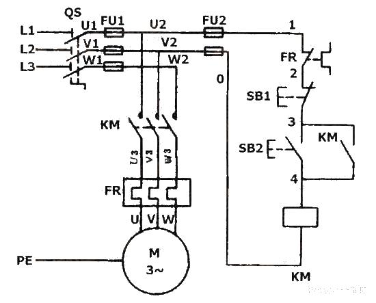
Electrical schematic diagram of self-locking forward rotation control circuit of three-phase asynchronous motor
Source: InternetPublisher:武林萌主 Updated: 2020/04/05
As shown in the figure, the main circuit of the self-locking control circuit of the three-phase asynchronous motor is roughly the same as the main circuit of the inching control, but a stop button SB1 is connected in series to the control circuit, and both ends of the start button SB2 are connected in parallel. A pair of normally open auxiliary contacts of the contactor KM. The contactor self-locking forward control circuit not only enables the motor to run continuously, but also has an important feature, which is that it has undervoltage and loss of voltage (or zero voltage) protection. It is mainly composed of push button switch SB (used to start and stop the motor), AC contactor KM (used to turn on and off the power of the motor and voltage loss and undervoltage protection, etc.), thermal relay (used for motor overload protection), etc.

Electrical schematic diagram of self-locking forward rotation control circuit of three-phase asynchronous motor
Undervoltage protection: "Undervoltage" means that the line voltage is lower than the rated voltage that should be applied to the motor. "Undervoltage protection" refers to a protection that when the line voltage drops to a certain value, the motor can automatically disconnect from the power supply voltage and stop, preventing the motor from running under undervoltage. Because when the line voltage drops, the torque of the motor decreases and the speed of the motor also decreases, which increases the operating current of the motor and affects the normal operation of the motor. When the voltage drop is severe, it may cause "locked rotor" (That is, the motor is powered on but does not rotate), resulting in damage to the motor. Using a contactor self-locking forward control circuit can prevent the motor from running under voltage. This is because when the circuit voltage drops to a certain value (generally below 85% of the rated voltage), the voltage at both ends of the contactor coil also drops to A certain value, thereby weakening the magnetic flux of the contactor coil and reducing the electromagnetic attraction generated. When the electromagnetic suction force is reduced to less than the tension of the reaction spring, the moving iron core is forced to release, driving the main contacts and self-locking contacts to disconnect at the same time, automatically cutting off the main circuit and control circuit, and the motor loses power and stops, achieving under-voltage protection. the goal of.
Voltage loss (or zero voltage) protection: Voltage loss protection means that the motor can automatically cut off the power supply when there is a sudden power outage due to some external reason during normal operation. When re-powering, ensure that the motor cannot start on its own to avoid causing equipment and personal casualties. The contactor self-locking control circuit is used. Since the contactor self-locking contact and the main contact have been disconnected when the power is turned off, neither the control circuit nor the main circuit can be connected. Therefore, when the power supply is restored, the motor cannot start running by itself, ensuring the safety of people and equipment.
The control principle of the self-locking control circuit of the three-phase asynchronous motor: when the start button SB2 is pressed, the power supply U1 phase passes through the thermal relay FR movable breaking contact, the movable breaking contact of the stop button SB1, the movable closing contact of the start button SB2 and the AC contactor KM The coil of the AC contactor is connected to the V1 phase of the power supply, causing the AC contactor coil to be charged and activated, and its main contact is closed to cause the motor to rotate. At the same time, the normally open auxiliary contact of the AC contactor KM short-circuits the moving contact of the start button SB2, keeping the AC contactor coil in a charged state at all times. This is the so-called self-locking (self-protection). The normally open auxiliary contact that is connected in parallel with the start button SB2 and has a self-locking function is called a self-locking contact (or self-protecting contact).
- Manual automatic air compressor control circuit
- Motor self-starting circuit
- Motor control circuit for starting and running without phase loss
- Design and analysis of voice control circuit
- Do-it-yourself trial production of phase failure protection device
- Design and manufacture of three-phase motor protection circuit
- A novel and practical power line anti-theft and cutting alarm circuit
- Homemade anti-theft watchdog
- Control two contactors with one wire
- Solar Flash Light
- Homemade disinfectant circuit
- Photocell amplification control circuit
- Multi-pole leakage protector circuit b
- The structure of Hisense KFR-25GW-06BP inverter air conditioner outdoor unit microprocessor control circuit
- Photoelectric output control circuit
- Relay control circuit a
- Taifu DK2-25 rice cooker temperature detection control circuit
- Temperature detection control circuit of electric hot water bottle
- Voltage servo motor and control circuit
- DC motor forward and reverse control circuit


 京公网安备 11010802033920号