How to use "virtual short" and "virtual break" to analyze op amp circuits
Source: InternetPublisher:国民男神经 Keywords: Power supply regulated power supply Updated: 2020/01/08
Operation is a very important component in analog circuits. It can form various circuits such as amplification, addition, subtraction, conversion, etc. It is not difficult to analyze op amp circuits faster and more accurately. That is to use the "virtual short" and "virtual open" of the op amp to analyze the circuit, and then apply Ohm's law and other current-voltage relationships to get the input-output amplification relationship, etc.
The following is a brief explanation of how to use "virtual short" and "virtual break" to analyze op amp circuits.
Method/steps
About virtual shortness and virtual break
Since the voltage amplification factor of the operational amplifier is very large, the open-loop voltage amplification factor of general general-purpose operational amplifiers is above 80dB. The output voltage of the op amp is limited, generally between 10V and 14V. Therefore, the differential mode input voltage of the op amp is less than 1mV, and the two input terminals are approximately at the same potential, which is equivalent to a "short circuit". The greater the open-loop voltage amplification, the closer the potentials at the two input terminals are to the same value. "Virtual short circuit" means that when the operational amplifier is in a linear state, the two input terminals can be regarded as equal potential. This characteristic is called a false short circuit, or virtual short circuit for short. Obviously the two input terminals cannot be truly short-circuited. Since the differential mode input resistance of the operational amplifier is very large, the input resistance of general-purpose operational amplifiers is above 1MΩ. Therefore, the current flowing into the input terminal of the op amp is often less than 1uA, which is much smaller than the current of the external circuit at the input terminal. Therefore, the two input terminals of the op amp can usually be regarded as open circuit, and the greater the input resistance, the closer the two input terminals are to open circuit. "Virtual break" means that when the operational amplifier is in a linear state, the two input terminals can be regarded as equivalent open circuits. This feature is called a false open circuit, or virtual break for short. Obviously the two input terminals cannot be truly disconnected.
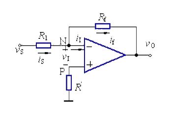
Example analysis. As shown in the figure, it is a common inverting proportional operational amplifier circuit. The following uses the virtual short and virtual break methods to analyze the circuit.

In the inverting amplifier circuit, the signal voltage is added to the inverting input terminal of the op amp through the resistor R1, and the output voltage vo is fed back to the inverting input terminal of the op amp through the feedback resistor Rf, forming a voltage parallel negative feedback amplification circuit.
The non-inverting terminal of the op amp is grounded = 0V, the inverting terminal and the non-inverting terminal are virtual short, so they are also 0V. The input resistance of the inverting input terminal is very high, virtual open, and there is almost no current injection and outflow, then R1 and Rf are equivalent to being connected in series. The current flowing through each component in a series circuit is the same, that is, the current flowing through R1 and the current flowing through Rf are the same.
According to Ohm's law:
Is=(Vs-V-)/R1…………a
If= (V--Vo)/Rf……b
V-=V+=0………………c
Is=If……………………d
After solving, it may be Vo==(-Rf/R1)*Vi
In the process of analyzing the circuit, we don't need to worry about other characteristics of the op amp for the time being, and we will analyze it based on the characteristics of virtual short and virtual break. Of course, if the op amp is not working in the amplification area and does not meet the conditions of virtual short and virtual break, this method cannot be used for analysis. Such as comparator.
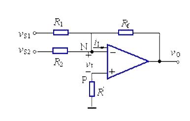
As shown in the figure below, it is an adder implemented by an op amp. This circuit is analyzed using the methods of virtual short and virtual break.
Due to the virtual short in the circuit, the net input voltage vI of the op amp is 0, and the inverting terminal is virtual ground.
vI=0, vN=0…………………………………………a
The concept of the inverting terminal input current iI=0, the sum of the currents passing through R2 and R1 is equal to the current passing through Rf, so (Vs1–V-)/R1+(Vs2–V-)/R2=(V-–Vo)/Rf …………b.
If we take R1=R2=R3, and solve the two equations a and b, we get -Vout=Vs1+Vs2.
The negative sign in the formula is caused by the inverting input. If another stage of inverting circuit is connected, the negative sign can be eliminated.

Virtual short means that the voltages at the positive and negative input terminals of the op amp are equal, which is approximately a short circuit; virtual open means that the current flowing into the positive and negative input terminals is 0. As long as you master this point and use Ohm's law, you can easily analyze common op amp amplifier circuits such as in-phase proportional amplification circuits and inverse proportional amplification circuits.
- In-depth analysis of DC-AC converter inverter
- 220V Remote Load Monitor
- Driving circuit of switching power supply field effect tube
- INA155/INA156 is used to form a single-supply high-side current monitor for detecting load current
- Use pulse width modulation to get a precise output voltage
- Parallel DC regulated power supply circuit diagram
- A small and easy-to-make fast charger
- USB power socket using the car battery
- A low-cost, high-reliability battery charger for electric vehicles
- Circuit diagram explanation: simple switching power supply circuit diagram
- 24V power supply pure flat display high voltage power supply circuit diagram
- Power supply circuit with multiple outputs (MAX1902)
- 2-phase CPU power supply circuit using HIP6302 and HIP6602 chips
- Timing switch AC power circuit
- Recording level power supply circuit
- Diamond differential input power amplifier power circuit
- Super Class A power amplifier power circuit
- Karaoke light controller circuit (1)
- Practical neon light power circuit
- CTX-C2 dual-band high-resolution color display power circuit


 京公网安备 11010802033920号