PFC design analysis to realize three-phase uncontrolled rectification circuit
Source: InternetPublisher:D先生 Keywords: Power supplyAC/DC Updated: 2020/08/31
PFC technology has been successfully applied in the design process of small and medium-power switching power supply products. Through the reasonable use of power factor correction, engineers can effectively improve their work efficiency. In today's article, we will use a practical case to analyze it for new engineers to see how to effectively implement PFC design in a three-phase uncontrolled rectifier circuit.
The three-phase uncontrolled rectifier circuit is a relatively common circuit design type in the design of small and medium-power switching power supplies. However, this circuit system also has its own shortcomings, that is, even if the load is equivalent to a resistor, a satisfactory power factor cannot be obtained, and manual PFC design is required. The fundamental reason for this problem is that the three-phase voltages in the three-phase uncontrolled rectifier circuit are coupled to each other through the uncontrolled rectifier bridge. The input current is a function of the three-phase voltages. It is impossible to take into account the three-phase input current at the same time, so that any one phase The input current cannot be independently controlled into a sinusoidal waveform, and the three-phase input voltage must be decoupled. In the figure below, Figure 1 shows the structure of a three-phase uncontrolled rectifier circuit with large capacitor filtering.
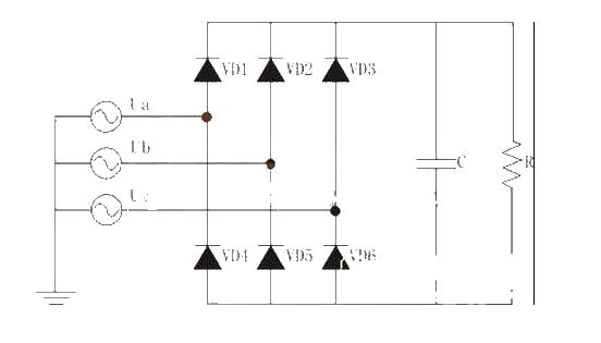
Figure 1 Three-phase uncontrolled rectifier circuit with large capacitor filter
Combined with the circuit structure shown in Figure 1, let's simulate and analyze the three-phase uncontrolled rectifier circuit with large capacitor filtering. During the simulation process, the parameters we set are as follows: input phase voltage effective value Ui=220V/50Hz, output filter capacitor C=1800μF, load R=50Ω. The input phase voltage and phase current waveform of any phase is shown in Figure 2. Figure 3 is the harmonic analysis diagram of the input current. The power factor value measured by the simulation is 0.566. It can be seen from the simulation results that this circuit has the disadvantages of low power factor, large total harmonic distortion of the input current, and seriously excessive input harmonic current content.
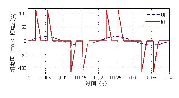
Figure 2 Input voltage and current waveform of three-phase uncontrolled rectifier circuit with large capacitor filter
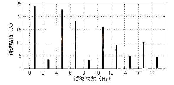
Figure 3 Analysis of input current harmonics of three-phase uncontrolled rectifier circuit with large capacitor filtering
After understanding the shortcomings of this large-capacitance filtered three-phase uncontrolled rectifier circuit, in view of its own shortcomings, the PFC improvement method we adopted is to use an LC filter before the bridge and a reactor after the bridge to A circuit system is redesigned to achieve the purpose of PFC (power factor correction). A three-phase passive PFC circuit using an LC filter before the bridge and a reactor behind the bridge is shown in Figure 4. Its characteristic is that passive filter inductors and capacitors are added to the AC input side of the original three-phase full-bridge rectifier circuit. Each phase of the AC input terminal is connected in series with a filter inductor L, and the input filter capacitor C adopts a delta connection. At the same time, a reactor is connected in series before the load after the rectifier bridge of the original three-phase uncontrolled rectifier circuit.
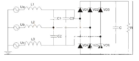
Figure 4 A three-phase passive PFC circuit using an LC filter before the bridge and a reactor after the bridge
After understanding the design of the three-phase passive PFC circuit introduced in Figure 4, which uses an LC filter before the bridge and a reactor after the bridge, we will conduct Matlab software simulation research on this three-phase passive PFC circuit. . The settings of the main simulation parameters are as follows: the three-phase AC input voltage is Ui=220V/50Hz. Input filter capacitor parameters C1=C2=C3=20μF, input filter inductor parameters L1=L2=L3=10mH, three-phase rectifier bridge output filter capacitor C=1800μF, inductor L=15mH, load resistance R=50Ω.
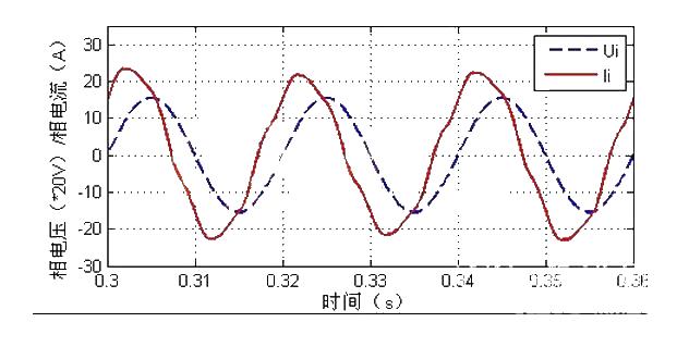
Figure 5(a) Input voltage and current waveform of a three-phase passive PFC circuit using an LC filter before the bridge and a reactor after the bridge
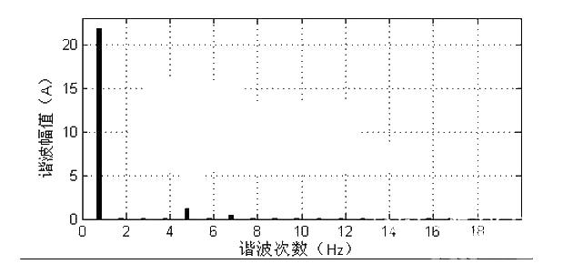
Figure 5(b) Input current harmonic analysis of a three-phase passive PFC circuit using an LC filter before the bridge and a reactor after the bridge
After simulation, the simulated waveforms of the input phase voltage Ui and phase current ii of this circuit with PFC design and the harmonic analysis diagram of the input current are shown in Figure 5(a) and (b) respectively. After measurement, the power factor value is 0.804 and the total harmonic distortion rate THD=15.3%. By comparing the simulation results shown in Figure 5 with Figure 3, it is found that adding an LC passive filter to the AC input end of this three-phase uncontrolled rectifier circuit can effectively reduce the THD value of the input phase current and improve the The power factor of the circuit. Compared with the reactor without series connection, the current waveform of the reactor connected in series after the rectifier bridge is significantly improved.
- TPS274C65 helps reduce downtime and increase productivity in 24 VDC power distribution plants
- Isolated two-wire current loop circuit (XTR101, ISO100)
- The constant current source composed of two transistors can drive high power
- Using CW34603 to form a circuit to change the polarity of the output power supply
- 0.7~24V continuously adjustable current limiting power supply
- USB power socket using the car battery
- Electric bicycle battery charger circuit
- UC3842 Electric Vehicle Charger
- A low-cost, high-reliability battery charger for electric vehicles
- LM317T voltage regulation adjustable circuit diagram explanation
- Principle of single live wire power taking circuit
- Delay pull-in relay switch control circuit diagram
- Three-phase electricity meter wiring circuit diagram
- Zero-crossing trigger circuit diagram based on thyristor
- Two-wire remote AC electronic thermostat (gas or oil furnace control)
- Photoresistor can form a bridge photodetector circuit diagram
- Portable device charging power circuit design
- 3v to 5v circuit diagram
- Three-way DC-DC converter circuit
- Single LTC power circuit


 京公网安备 11010802033920号