Production of high-performance active anti-magnetic speakers 02
Source: InternetPublisher:toothache Keywords: Speaker BSP potentiometer Updated: 2020/06/12

The dual-channel karaoke circuit is shown in Figure 9-60. The core component of this circuit is a professional reverberation karaoke
chip from Panasonic Corporation of Japan. The vocal signal sent from the microphone input end
is divided into : one channel is directly fed to 1VT6, and the other channel is filtered and amplified by IVT3 and then fed into the delay loop composed of lcl and 1C2. Delay processing is performed
, and then filtered and amplified by 1VT4 and 1VT5. The signal output by 1VT2 is mixed and amplified at IVT6
to output a vocal accompaniment signal with a reverberation effect; 1RP1 in Figure 9-60 is the microphone volume control potentiometer. , 1RP2 is
the reverberation depth control potentiometer.
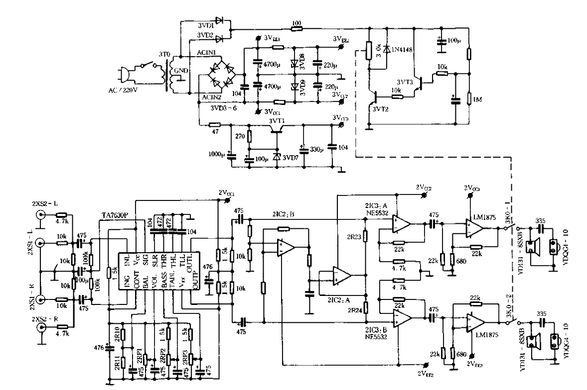
The signal input and tone control circuit is shown in Figure 9-61. The signal input circuit is designed for two sets of high and low level inputs.
2xsl is a high-level input terminal, and 2XS2 is a low-level input terminal. In actual use, you can first try to input the signal from the high-level input terminal
. If the output power cannot meet the requirements, then try to input the signal from the low-frequency terminal. This can avoid overload signals at the speaker output terminal;
the tone control circuit is specially designed for tone control by Toshiba Corporation of Japan. It is composed of integrated circuit TAP7630P and its peripheral devices. It has
the function of single-ended DC potential to control the high and low tones, balance and volume of two channels. Since the balance potentiometer is not used in a
high amount, in order to reduce the impact of external adjustment Inconveniently, this design uses 2R10 and ZR11 balance resistors to always lock the balance control potential
in a balanced state; in Figure 9-61, 2RP1 is the volume control knob, 2RP2 is the bass control knob, and 2RP3 is the treble control
knob.
- Simple and convenient remote control receiver dual purpose detector
- Temperature Range Monitoring System
- DIY Multimeter High Frequency Signal Probe
- A circuit for qualitatively testing capacitor leakage
- Simple and easy to make zero degree detector
- Low resistance connection tester circuit diagram sharing
- Production of acoustic and optical digital level detector
- Use LM3915 to make a practical audio power meter
- Digitally controlled operational amplifier gain circuit
- Phase sequence indicator circuit diagram
- soil content measurement circuit
- Rural vegetable greenhouse lighting circuit
- Straw returning to field crusher circuit
- Farmland irrigation automatic control circuit a
- Double detuned loop frequency discriminator circuit
- Frequency modulator composed of NE566
- Integrated synchronous detector composed of analog multiplier MC1596
- Second-order active band-stop filter circuit
- Voltage controlled power supply second-order high-pass filter circuit
- Small current generator circuit


 京公网安备 11010802033920号