How to Interface PCF8591 ADC Module with Raspberry Pi
Source: InternetPublisher:偷熊计划 Keywords: adc analog-to-digital converter PCF8591 Updated: 2024/12/27
Analog to digital conversion is a very important task in embedded electronics as most of the sensors provide their output in the form of analog values and feeding them to a microcontroller which understands only binary values, we have to convert them into digital values. So, to be able to process analog data, microcontrollers require analog to digital converters.
In this tutorial, we will learn how to interface PCF8591 ADC/DAC module with Raspberry Pi.
Required Components
Raspberry Pi
PCF8591 ADC Module
100K Pot
Jumper cables
It is assumed that you have a Raspberry Pi with the latest Raspbian OS installed and that you know how to connect to the Pi via SSH using terminal software such as putty. If you are new to Raspberry Pi, follow this article to get started with Raspberry Pi. Nonetheless, if you run into any problems, there are plenty of Raspberry Pi tutorials that can help.
PCF8591 ADC/DAC module
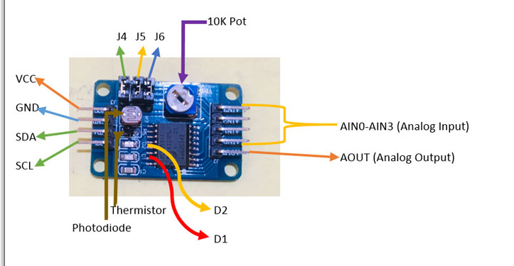
PCF8591 is an 8-bit analog-to-digital or 8-bit digital-to-analog converter module, which means each pin can read up to 256 analog values. It also has LDR and thermistor circuits provided on the board. The module has four analog inputs and one analog output. It is suitable for I2C communication, so there are SCL and SDA pins for serial clock and serial data address. It requires a supply voltage of 2.5-6V and has a low standby current. We can also control the input voltage by adjusting the knob of the potentiometer on the module. There are also three jumpers on the board. J4 selects the thermistor access circuit, J5 selects the LDR/photoresistor access circuit and J6 selects the adjustable voltage access circuit. There are two LEDs D1 and D2 on the board - D1 shows the output voltage intensity and D2 shows the supply voltage intensity. The higher the output or supply voltage, the higher the intensity of LED D1 or D2. You can also test these LEDs using the potentiometer on the VCC or AOUT pins.
I2C pins in the Raspberry Pi
In order to use PCF8591 with Raspberry Pi, the first thing to do is to understand the Raspberry Pi I2C port pinout and configure the I2C port in Raspberry pi.
Below is the pin diagram for the Raspberry Pi 3 Model B+. This tutorial uses the I2C pins GPIO2 (SDA) and GPIO3 (SCL).
Configuring I2C on the Raspberry Pi
By default, I2C is disabled in the Raspberry Pi. So first you have to enable it. Enable I2C in Raspberry Pi
1. Go to terminal and type sudo raspi-config.
2. Now the Raspberry Pi Software Configuration Tool appears.
3. Select Interface Options and enable I2C.
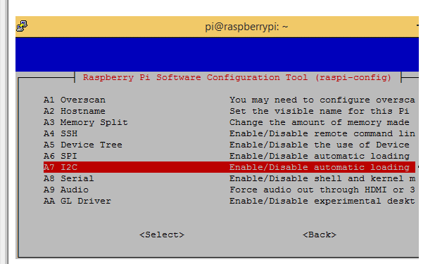
4. Reboot the Pi after enabling I2C.
Use Raspberry Pi to scan the I2C address of PCF8591
Now in order to start communicating with the PCF8591 IC, the Raspberry Pi must know its I2C address. To find the address, first connect the SDA and SCL pins of the PCF8591 to the SDA and SCL pins of the Raspberry Pi. Also connect the +5V and GND pins.
Now open the terminal and type the following command to know the address of the connected I2C device,
sudo i2cdetect –y 1 or sudo i2cdetect –y 0
Now that the I2C address has been found, it is time to build the circuit and install the necessary libraries to use the PCF8591 with the Raspberry Pi.
Connecting PCF8591 ADC/DAC Module to Raspberry Pi
The circuit diagram for interfacing PCF8591 with Raspberry Pi is simple. In this interfacing example, we will read the analog values from any analog pin and display it on the Raspberry Pi terminal. We can use a 100K pot to change these values.
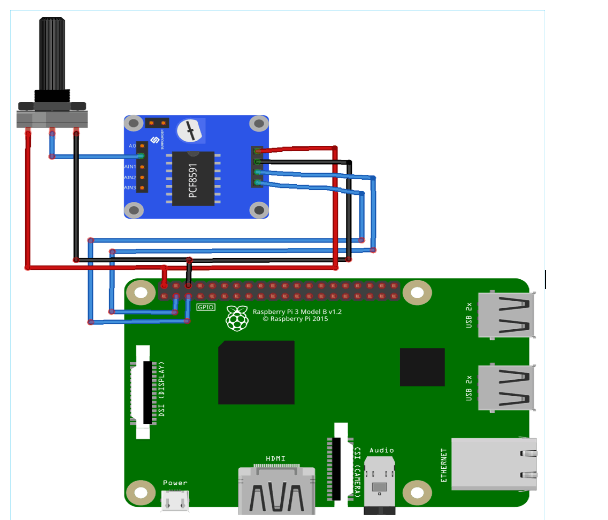
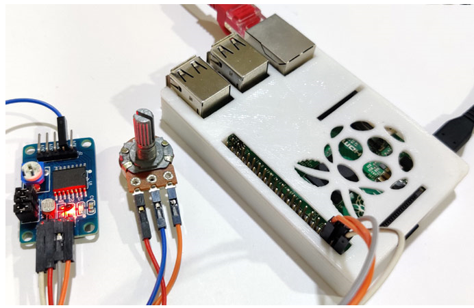
Connect VCC and GND to GPIO2 and GPIO 0 of the Raspberry Pi. Next, connect SDA and SCL to GPIO3 and GPIO5 respectively. Finally, connect a 100K potentiometer with AIN0. You can also add a 16x2 LCD to display the ADC value instead of displaying it on the terminal.
Python Program for Analog-to-Digital Conversion (ADC)
First, import the smbus library for I2C bus communication and the time library to provide sleep time between printing values.
Import smbus
Import time
Now let's define some variables. The first variable will contain the address of the I2C bus and the second variable will contain the address of the first analog input pin.
Address = 0x48
A0 = 0x40
Next, we created an object of the SMBus(1) function of the smbus library.
bus = smbus.SMBus(1)
Now, the first line tells the IC to take an analog measurement on the first analog input pin. The second line stores the address read at the analog pin in the variable value. Finally the value is printed.
while True:
    bus.wri
Now finally save the python code in a file with .py extension and run the code in the raspberry pi terminal using the following command "
python filename.py
Now finally save the python code in a file with .py extension and run the code in the raspberry pi terminal using the following command "
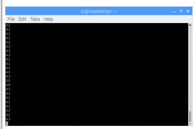
Before running the code, make sure you have enabled I2C communication and all the pins are connected as shown in the diagram, otherwise it will display an error. The analog values must start displaying on the terminal as shown below. Adjust the knob of the pot and you will see a gradual change in the values.
import smbus
import time
address = 0x48
bus = smbus.SMBus(1)
while True:
bus.write_byte(address,A0)
value = bus.read_byte(address)
print(value) time.sleep
(0.1)
- Introduction to the use of UnoArduSim
- Temperature and clock display
- Circuit diagram of multifunctional digital clock
- Improved circuit diagram of 8050 transistor emitter drive relay
- Phase-locked loop controller using AT89S51 microcontroller
- Interface circuit between MMA1220D and microcontroller
- Serial debugger circuit implemented with several discrete components
- 815ept motherboard
- Circuit diagram: AT88RF
- Microcontroller test board circuit three
- Analysis of the importance of reference voltage source
- Circuit composed of ADC 0808-ADC 0809 chips
- Typical channel monitoring circuit diagram
- Using ICL7107 digital voltmeter circuit diagram
- Rectifier circuit without diodes
- Successive Approximation Analog-to-Digital Converter
- Connection circuit between sensor and A/D converter ADC614
- ADC circuit schematic diagram
- AD7730 sensor ADC circuit
- ADC circuit


 京公网安备 11010802033920号