How to build an Atmega16 based digital wall clock using DS3231
Source: InternetPublisher:难得正经 Keywords: ATmega16 DS3231 digital clock Updated: 2024/12/27
Every digital clock has a crystal inside to keep track of the time. This crystal is not only present in clocks but in all computing real-time systems. This crystal generates the clock pulses which are required for timing calculations. Although there are some other ways to get clock pulses with higher accuracy and frequency, the most preferred method is to use a crystal to keep track of the time. Here, we will build an Atmega16 based digital wall clock with DS3231 RTC IC. DS3231 RTC has a high accuracy crystal inside so no external crystal oscillator is required.
In this digital clock project, ten 0.8 inch common anode 7 segment displays are used to display the time and date. A seven segment display is used here to display the hours, minutes, date, month, and year. Our PCB design also has the option to display seconds and temperature which can be displayed by adding more display units.
Required Components
ATmega16 AVR Microcontroller
DS3231 Real-Time Clock Integrated Circuit
Common anode 0.8-inch seven-segment display (larger than normal size display (0.56-inch))
Button
Button battery 3v
7805 Voltage Regulator
1000uf capacitor
Buzzer (optional)
Transistors BC547 and BC557
10uf capacitor
100 Ohm Resistor
1k resistor
10k resistor
PCB board
Jumper Wires
Tips
Power adapter
Users can also use an Atmega32, which will need to be configured in the compiler before generating hex.
Circuit diagram and description
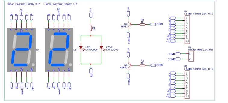
This digital wall clock circuit has two parts, one is the display part which has 5 pairs of 7 segments on five different PCB boards and the other is the control unit part which is responsible for getting the time from the RTC chip and sending the data and time to the 7 segment display. Since we have used 10 seven segment displays, we cannot connect each display to a separate IO port. So, multiplexing technique is used here to connect multiple seven segments using fewer microcontroller pins.

The LED pins a, b, c, d, e, f, g, h of the seven segment display are connected in parallel to PORTB of atmega16. Here we have used 10 seven segment displays, so we need 10 control pins connected to PORTD, PORTA and PORTC.
The RTC DS3231 with internal crystal is connected to the SDA and SCL pins of PORTC as this chip works on I2C communication. The interfacing method of this chip is the same as that of DS1307. We have used DS1307 with Arduino, Raspberry Pi and 8051 MCU. The same code can be used for both DS3231 and DS1307.
Two 10k pull-up resistors are connected on the SDA and SCL lines. A 3v button cell battery is used to power the RTC chip to keep track of the time even when the main power is off. Whenever the power is restored again, the time will start displaying on the seven segment display. Now we have some buttons at PORT A for setting the time, the complete process is explained in the video given at the end. A 5v regulator is used to convert the input voltage to 5v. All the connections are shown in the circuit diagram below:

For one display board, two seven segment displays and 2 LEDs are used. So here we have five different display boards to show the time in hours and minutes (HH-MM), and the date in DD-MM-YY.

PCB design and manufacturing of digital clocks
For this Atmega16 based wall clock project, we have designed two PCBs. One is the control unit, which is used to control all the operations of the project, and the second is used to display the time and date on the seven-segment display. The display part contains five pairs of 0.8-inch seven-segment displays. So, by assembling 5 parts, we have a complete digital clock. To multiplex the 7-segment display, the data lines of the 5 PCBs will be connected to the same port of the control unit, and the control lines are connected to different pins of the control unit.
Below are the top and bottom views of the PCB layout for a display board consisting of two seven-segment displays:
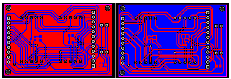
Below is the top and bottom view of the control unit PCB

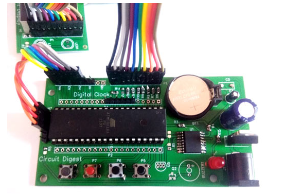
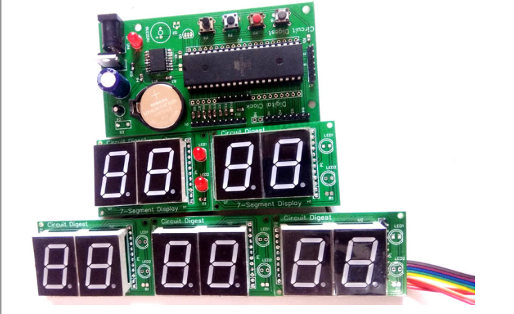
A few pictures of the board after soldering are shown below.
Testing the Digital Clock
The complete code is given at the end of this tutorial, just connect the PCB as per the circuit diagram and upload the code to Atmega16. You will see the time and date on ten seven segment displays.
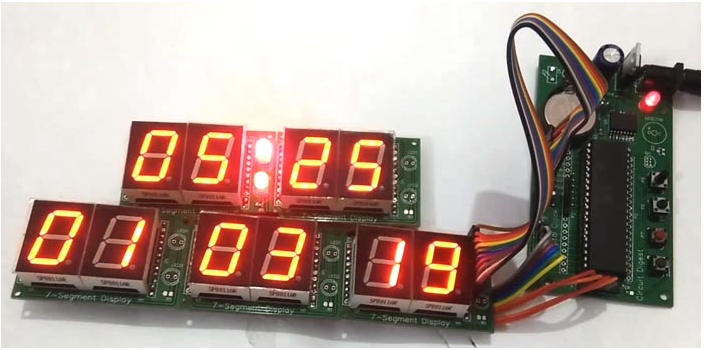
The time and date can be set using the four buttons on the control unit.
/*
* Digital clock.c
#include
#define F_CPU 8000000UL
#include
#include
int day=6,dd=1,mm=3,yy=19;
Unsigned integer seconds, minutes=13, hours=4;
const unsigned integer[] = {0X40,0X79,0X24,0X30,0X19,0X12,0X02,0X78,0X00,0X10};
int d0,d1,d2,d3,d4,d5,d6,d7,d8,d9;
volatile unsigned integer count, count 1;
#define number 13
#define data port PORTB
#define controlPortD port
#define controlPortC PORTC
#define controlPortA PORTA
#define controlPortD_Mask 0x83
#define controlPortC_Mask 0x03
#define controlPortA_Mask 0x7F
#define segment close -1
#define sw PINA
#Define set 4
#define 3
# Define upward 2
#define 1 downward
#define se tEvent (sw & (1<))<>
#define okEvent (sw & (1<))<>
#define upEvent (sw & (1<))<>
#define downEvent (sw & (1<))<>
#define LEDPORT PORTA
#define secLed 5
#define BUZPORT port
#define BUZZER 7
Character flashing sign;
Volatile character onFlag = 0x00;
#define timeFormat 24
enumerate
{
hour = 1,
minute,
date,
moon,
Year,
};
Character segOn[12] = {0x04, 0x08, 0x10, 0x20, 0x40, 0x80, 0x40, 0x80, 0x10, 0x20, 0x04, 0x08};
void display();
void updateTime();
ISR (TIMER1_OVF_vect)
{
exhibit();
TCNT1 = 64000;
}
Invalid select segment (integer count)
{
if (count < 5)
{
controlPortA&=controlPortA_Mask;
controlPortC&=controlPortC_Mask;
controlPortD&=controlPortD_Mask;
controlPortD|=segOn[count];
}
else if (count == 5)
{
controlPortA|=segOn[count];
controlPortC&=controlPortC_Mask;
controlPortD&=controlPortD_Mask;
}
else if (count == -1)
{
controlPortA&=controlPortA_Mask;
controlPortC&=controlPortC_Mask;
controlPortD&=controlPortD_Mask;
}
Other
{
controlPortA&=controlPortA_Mask;
controlPortC&=controlPortC_Mask;
controlPortD&=controlPortD_Mask;
controlPortC|=segOn[count];
}
}
void segment(int count, int segment)
{
if (blinkflag == segment)
{
if (onFlag)
selectSegment(segmentClose);
Other
selectSegments(count);
}
Other
{
selectSegments(count);
}
}
void display()
{
count1++;
if (count1 > 400)
{
count1=0;
onFlag=!onFlag;
}
count++;
if (count > number)
count = 0;
Switch (count%digit)
{
Case 0:
Segment(count, minutes);
data_port = num[d0];
rest;
Case 1:
Segment(count, minutes);
data_port = num[d1];
rest;
Case 2:
Segment(count, hours);
data_port = num[d2];
rest;
Case 3:
Segment(count, hours);
data_port = numbers[d3];
rest;
Case 4:
Segment(count, date);
dataport = num[d4];
rest;
Case 5:
Segment(count, date);
data_port = numbers[d5];
rest;
Case 6:
segment(count,month);
data_port = digital[d6];
rest;
Case 7:
segment(count,month);
data_port = digital[d7];
rest;
Case 8:
segment(count,year);
data_port = digital[d8];
rest;
Case 9:
segment(count,year);
data_port = num[d9];
rest;
}
}
void timer1_init()
{
// Set up the timer with prescaler = 8
TCCR1B |= (1 << CS11);
//TCCR1B &= ~(1 << CS10);
//TCCR1B &= (1 << CS11);
//TCCR1B &= ~(1 << CS12);
TCNT1 = 63500;
TIMSK |= (1 << TOIE1);
sei();
}
int bcdtochar(number of characters)
{
return ((num/16 * 10) + (num % 16));
}
int decobcd(number of characters)
{
Return ((num/10)<<4) + (num % 10);
}
void RTC_start()
{
TWCR=(1<)|(1<
while ((TWCR&0x80)==0x00);
}
void device()
{
TWDR = 0xD0; //RTC write (slave address)
TWCR=(1<)|(1<
while(!(TWCR&(1<)));<>
TWDR=0x00; //word address write
TWCR=(1<)|(1<
while(!(TWCR&(1<)));<>
}
void RTC_stp()
{
TWCR=(1<)|(1<
}
void RTC_read ()
{
TWCR=(1<)|(1<
while ((TWCR&0x80)==0x00);
TWDR = 0xD0; //RTC write (slave address)
TWCR=(1<)|(1<
while(!(TWCR&(1<)));<>
TWDR = 0x00; //RTC write (word address)
TWCR=(1<)|(1<
while(!(TWCR&(1<)));<>
TWCR=(1<)|(1<
while ((TWCR&0x80)==0x00);
TWDR=0xD1; //RTC command read
TWCR=(1<)|(1<
while(!(TWCR&(1<)));<>
}
void sec_init(unsigned char d)
{
TWDR=d; //Second initialization
TWCR=(1<)|(1<
while(!(TWCR&(1<)));<>
}
void min_init(unsigned char d)
{
TWDR=d; //Minute initialization
TWCR=(1<)|(1<
while(!(TWCR&(1<)));<>
}
void hr_init(unsigned char d)
{
TWDR=d; //Hour initialization
TWCR=(1<)|(1<
while(!(TWCR&(1<)));<>
}
void day_init(unsigned char d)
{
TWDR=d; //Day initialization
TWCR=(1<)|(1<
while(!(TWCR&(1<)));<>
}
void date_init(unsigned char d)
{
TWDR=d; //Date initialization
TWCR=(1<)|(1<
while(!(TWCR&(1<)));<>
}
void month_init(unsigned char d)
{
TWDR=d; //Month initialization
TWCR=(1<)|(1<
while(!(TWCR&(1<)));<>
}
void yr_init(unsigned char d)
{
TWDR=d; //Year initialization
TWCR=(1<)|(1<
while(!(TWCR&(1<)));<>
}
int sec_rw()
{
Int g[3];
TWCR|=(1<)|(1<
while ((TWCR & 0x80) == 0x00);
return bcdtochar(TWDR);
}
int min_rw()
{
TWCR|=(1<);>
TWCR|=(1<);<>
while ((TWCR & 0x80) == 0x00);
return bcdtochar(TWDR);
}
int hr_rw()
{
TWCR|=(1<)|(1<
while ((TWCR & 0x80) == 0x00);
return bcdtochar(TWDR);
}
int day_rd()
{
TWCR|=(1<)|(1<
while ((TWCR&0x80)==0x00);
return bcdtochar(TWDR);
}
int date_rw()
{
TWCR|=(1<)|(1<
while ((TWCR & 0x80) == 0x00);
return bcdtochar(TWDR);
}
int month_rw()
{
TWCR|=(1<)|(1<
while ((TWCR & 0x80) == 0x00);
return bcdtochar(TWDR);
}
int yr_rw()
{
TWCR|=(1<);>
TWCR&=(~(1<));<>
while ((TWCR & 0x80) == 0x00);
return bcdtochar(TWDR);
}
void setTime()
{
RTC_start();
equipment();
sec_init(0);
min_init(dectobcd(min));
hr_init(dectobcd(hr));
day_init(dectobcd(day));
date_init(dectobcd(dd));
month_init(dectobcd(mm));
yr_init(dectobcd(yy));
RTC_stp();
}
void RTC()
{
RTC_read();
sec=sec_rw();
min=min_rw();
hr = hr_rw();
day=day_rd();
dd = date_rw();
mm = month_rw();
yy=yr_rw();
RTC_stp();
}
char getPara(number of characters)
{
And (1)
{
updateTime();
if (!upEvent)
{
count1=0;
onFlag=0x00;
count++;
if (blinkingflag == hours)
{
if (timeformat == 12)
{
if (count > 12)
count = 0;
}
Other
{
if (count > 23)
count = 0;
}
hours = count;
}
else if (blinkFlag == minutes)
{
if (count > 59)
count = 0;
minutes = count;
}
else if (blinkFlag == month)
{
if (count > 12)
count = 1;
mm = count;
}
else if (blinkFlag == date)
{
if(mm == 4 || mm == 6 || mm == 9 || mm == 11)
{
if (count > 30)
count = 1;
}
Otherwise if(mm == 1 || mm == 3 || mm == 5 || mm == 7 || mm == 8 || mm == 10 || mm == 12)
{
if (count > 31)
count = 1;
}
Other
{
int y=2000+yy;
if (y/4 == 0 && y/400 == 0)
{
if (count > 29)
count = 1;
}
Other
{
if (count > 28)
count = 1;
}
}
dd=count;
}
else if (blinkFlag == year)
{
if (count > 99)
count = 0;
YY=count;
}
_delay_ms(200);
}
else if (!(downEvent))
{
Count- ;
if (blinking_flag == year)
{
if (count < 0)
count = 99;
}
_delay_ms(100);
}
else if (!okEvent)
{
_delay_ms(1000);
Return count;
}
}
}
void setTime()
{
blinkingflag = 1;
hr = getPara(hr);
blink_flag++;
min = getPara (min);
blink_flag++;
dd = getPara (dd);
blink_flag++;
mm=getPara(mm);
blink_flag++;
yy=getPara(yy);
blink_flag = 0;
}
void updateTime()
{
d0=min%10;
d1=minutes/10;
d2=hr%10;
d3=hours/10;
d4=dd%10;
d5=dd/10;
d6=mm%10;
d7=mm/10;
d8=yy%10;
d9=yy/10;
}
int main(void)
{
unsigned long integer time;
DDRB = 0xff;
DDRA=0xE0;
port = 0x1e;
DDRD = 0xff;
DDRC = 0xff;
timer1_init();
And (1)
{
realtimeclock();
updateTime();
_delay_ms(500);
LEDPORT|=1<;<>
_delay_ms(500);
LEDPORT&=~(1<);<>
if (!setEvent)
{
setTime();
setTime();
}
}
}
- How to use the GPS module of STM32F103C8 to obtain location coordinates
- How to Program an Arduino via Bluetooth
- Using PIC microcontroller to make a temperature and humidity meter
- How to Design a Fan Cooling System Using a Microcontroller
- Make a capacitive soil moisture sensor using ESP32
- Circuit design analysis of smart car image recognition system
- Use PC’s RS232 port to control LED lights
- PC infrared interface
- Production of infrared receiving controller based on AT89C2051
- Microcontroller test board circuit three


 京公网安备 11010802033920号