Tutorial on making your own remote-controlled robotic arm
Source: InternetPublisher:toothache Keywords: Sensors Remote Control Arduino Robotic Arm Updated: 2024/12/31
A robotic arm that wirelessly mimics your hand movements through a sensor-laden glove.
It consists of an artificial hand controlled by a glove with flexible sensors. The artificial hand reproduces the movements of the hand wirelessly by controlling the glove. Both the hand and the glove work with Arduino.
Step 1: Materials Required

Control Gloves Material:
• Elastic gloves;
• LilyPad Arduino board (there are different versions, usually with only 4 analog inputs, so pay attention and buy the one in the picture): it works exactly like the classic Arduino UNO, or you can even use an Arduino Nano directly;
• XBee modules: for radio communication;
•Shield connection to Xbee module;
• 5 bend sensors;
• 5 resistors: 47 KΩ;
• Battery pack with 3x1.5 V batteries (Lilypad can be powered from 2.7 to 5.5 V, so 4.5 V is fine);
• LilyPad FTDI Adapter: to connect the LilyPad board to the PC and load the program using the Arduino IDE (very optional as you can also use an Arduino UNO board removing the ATmega chip, but it's tricky to make this connection every time).
Material of the robotic arm:
•The palm is made of steel and the fingers are made of wood;
• Arduino UNO board;
• XBee modules;
• 5 servo motors 5V power supply (I used TowerPro SG90);
• Servo Shield for Arduino UNO: To connect the servo motors I used the Robot_Shield from FuturaElettronica, it also has a switching regulator to power the whole circuit, but you can use any shield for controlling servo motors. Link: https://store.open-electronics.org/index.php ?_rou... ;
• A shield to connect the XBee modules to (I made a horrible one, but it was economical and I needed to make a small one because of the size of the Robot_Shield);
•Fishing line;
• (Optional) A fishing sinker to secure the fishing line or simply tie a knot;
• 9 volt battery.
- Tools Required:
• Angle grinders (mainly used for cutting wood and steel);
•Axial grinding machines;
• Welding machine (with electrodes);
•drilling;
•Soldering station and solder;
• Electrician's scissors;
•pliers;
•Heat shrink tubing.
Step 2: Making the Gloves

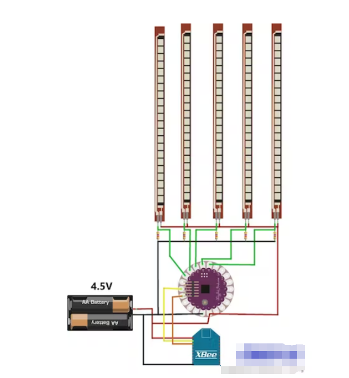
To make the control glove, I recommend first choosing the correct positions for the different components and then connecting everything with wires of appropriate lengths.
To do an analog reading with an Arduino LilyPad you need to make a voltage divider since flex sensors don't work like potentiometers (they only have 2 contacts).
So as per the plan, first solder 5 resistors on the LilyPad board, one side connected to 5 different analog pins and the other side connected to the common ground. Then solder the flex sensor, one side connected to 5 different analog pins and the other side connected to the positive terminal.
Then connect the XBee Shield: two wires for power and two for signal. Solder the Tx pin to the Rx and vice versa.
Now you need the battery pack and the gloves.
Note: Do not power the Arduino LilyPad with more than 5.5 V, and do not power it vice versa.
Step 3: Make the Robotic Arm

This is the most complicated part, as you have to choose the right material to make the hand, but it is also easy if you have the possibility to 3D print the hand (there are many different 3D projects online for printing hand parts).
I started making the fingers out of cork, finding the right structure for the action, and then made them out of branches.
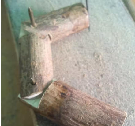
So make three wooden cylinders per finger, two of which are 1 cm longer than the normal length of your phalanges, and need to fit one piece into the other.
Then use an angle grinder to make grooves to make the parts fit together (see the pictures and you will understand better).
You'll need some sandpaper to bend the pieces so they can rotate.
Use a drill to make holes for the hinges, then you have to make two more holes for the fishing line, vertically, one towards the inside of the hand and one towards the outside. So when the wire is set on top of the fingers, the fingers will close when you pull inwards and open when you pull outwards.
But I later found out that the palm was problematic because I originally made it out of wood and the thinner part kept breaking. So I decided to make it out of steel and this time I had no problems.
Cut it and make some protrusions that resemble fingers to secure them to the palm (see the pictures for reference). Then use a drill to make the other holes for the fishing lines, the thumb will be tricky because it's not vertical like the other fingers.
Once you have your hands on it, you will need to make a support for the five servo motors and the Arduino UNO board. Be sure to choose the correct position for the servos so that they do not touch each other while rotating.
The last part is to connect the fingers to the servo motor: fix the fishing line on the top of the finger and pass it through the hole; then, when the wire is at the bottom of the hand, turn the rotor (manually, without power) at maximum rotation (180°) so that it is in vertical position, and set the wire of the closed finger to the hole of the lowest rotor, for example, with a knot; turn the rotor again by 0° (it is vertical again, with the previously tied knot at the top), and set the other wire (opening the finger) to the lowest hole of the rotor. Follow the last picture in this step for a better understanding.
So when the motor is at 0° (vertical), the fingers are open, and when the rotor is at 180° (vertical again), the fingers are closed.
Step 4: Circuit of the Robotic Arm

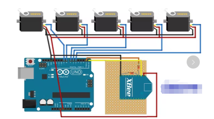
For the circuit, you can choose to use the Arduino UNO Servo Motor Shield with an XBee shield or make a custom shield using XBee modules and pins for the servo motors and power the Arduino UNO through its jack port.
The DIY XBee Shield I made uses a 12 KOhm resistor and a 22 KOhm resistor, you can see the wiring in the picture.
So I used something I already bought before, but you can use anything that lets you control servos and XBee.
The servo motor has 3 wires:
Yellow: signal (connected to a digital pin);
Red: power supply (+5 V);
Brown: Ground (GND).
I used the simplest servo motor that operates at 5 V and has a rotation angle of 180 degrees (which is the perfect angle, we don't need more).
The USB port of your computer cannot provide enough power to control 5 servos, so I recommend testing everything with a 12V power supply and then using a 9V battery (alkaline is preferred).
Step 5: Procedure
Remember: To load the program you must remove everything connected to the TX and RX pins of the Arduino (in this case the XBee modules), otherwise the program will not load. Also remember to set the correct type of Arduino in the IDE (LilyPad or Arduino UNO).
Links to both codes:
https://codebender.cc/sketch:59559
https://codebender.cc/sketch:55013
Try this code to test the elastic sensor on the glove: https://codebender.cc/sketch:56264
This is to test the connection between Lilypad and Arduino Uno: https://codebender.cc/sketch:55014
Untitled file:
/*
Flex Glove
Created by Santin Gabriele, 2014
I.T.S.T. "J. F. Kennedy", cl. 5^A EA
Thanks to Elias De Lamper for suggestions to improve this program!
*/
int ResThumb = A4; // Variables of the analog read form the flex sensors connected to the analog pins of Arduino LilyPad
int ResIndex = A3;
int ResMiddle = A2;
int ResAnnular = A1;
int ResPinky = A0;
int OpenedThumb =0; // Variables of the values when the hand is completely opened
int OpenedIndex =0; // This is needed for a continuous calibration
int OpenedMiddle =0;
int OpenedAnnular =0;
int OpenedPinky =0;
int ClosedThumb; // Variables of the values when the hand is completely closed
int ClosedIndex; // We can’t set it to zero since that the minimum value reached
int ClosedMiddle; // in the analog read never reach zero. We’ll assign the value of
int ClosedAnnular; // a first analog read, then the program in the loop will
int ClosedPinky; // automatically assing lower values
int thumb =0; // Variables of the values to send
int index =0;
int middle =0;
int annular =0;
int pinky =0;
void setup()
{
Serial.begin(9600); // Activating serial communication, XBee Series 1 are pre-programmed at 9600 baud/s
pinMode(ResThumb, INPUT); // The variables of the sensor are set as input
pinMode(ResIndex, INPUT);
pinMode(ResMiddle, INPUT);
pinMode(ResAnnular, INPUT);
pinMode(ResPinky, INPUT);
ClosedThumb = analogRead(ResThumb);
ClosedIndex = analogRead(ResIndex);
ClosedMiddle = analogRead(ResMiddle);
ClosedAnnular = analogRead(ResAnnular);
ClosedPinky = analogRead(ResPinky);
}
void loop()
{
thumb = analogRead(ResThumb);
index = analogRead(ResIndex);
middle = analogRead(ResMiddle);
annular = analogRead(ResAnnular);
pinky = analogRead(ResPinky);
if(thumb > OpenedThumb) // Calibration reading and setting the maximum values. This needs you to completely open your hand a few times
OpenedThumb = thumb;
if(index > OpenedIndex)
OpenedIndex = index;
if(middle > OpenedMiddle)
OpenedMiddle = middle;
if(annular > OpenedAnnular)
OpenedAnnular = annular;
if(pinky > OpenedPinky)
OpenedPinky = pinky;
if(thumb < ClosedThumb) // Calibration reading and setting the minimum values. This needs you to completely close your hand a few times
ClosedThumb = thumb;
if(index < ClosedIndex)
ClosedIndex = index;
if(middle < ClosedMiddle)
ClosedMiddle = middle;
if(annular < ClosedAnnular)
ClosedAnnular = annular;
if(pinky < ClosedPinky)
ClosedPinky = pinky;
thumb = map(thumb ,ClosedThumb ,OpenedThumb ,0,180); // The analog read has to be readapted in values between 0 and 180 to be used by the servomotors.
index = map(index ,ClosedIndex ,OpenedIndex ,0,180); // The minimum and maximum values from the calibrations are used to correctly set the analog reads.
middle = map(middle ,ClosedMiddle ,OpenedMiddle ,0,180);
annular = map(annular,ClosedAnnular,OpenedAnnular,0,180);
pinky = map(pinky ,ClosedPinky ,OpenedPinky ,0,180);
Serial.write("<"); // This character represent the beginning of the package of the five values
Serial.write(thumb); // The values are sent via the Tx pin (the digital pin 1)
Serial.write(index);
Serial.write(middle);
Serial.write(annular);
Serial.write(pinky);
delay(30);
}
- How to choose the right level of integration to meet motor design requirements?
- How to Make a Hot Tub Smart and Remotely Operated with a Raspberry Pi
- A small improvement to the temperature and water level indicator alarm
- Working principle of one Xipu STR soft starter controlling two motors
- One-way rotation circuit of motor controlled by contactor
- Home wireless burglar alarm circuit
- Car audio system anti-theft circuit
- Password type motorcycle anti-theft device
- Vibration anti-theft alarm circuit
- Rolling door anti-theft device
- X-Class CMOS sensor, do you know it?
- Car ignition circuit diagram based on FM484 magnetic induction
- Intelligent fire alarm system circuit module design
- Color sensor amplification circuit
- AD7730 internal functional block diagram and pin function diagram
- Photo machine automatic exposure drive circuit
- Identification sensor amplification circuit diagram
- Bridge sensor transmit/receive circuit
- Sensors and REF19X Series Precision Low Output Voltage Reference Circuits
- Sensor analog signal input ADC701/SHC702 circuit


 京公网安备 11010802033920号