How to measure short circuit and ground with a multimeter
Source: InternetPublisher:子丑寅卯 Keywords: Multimeter ground short circuit Updated: 2025/01/21
Use a multimeter to measure short circuit and grounding. What we are talking about here is basically strong electricity. In fact, weak electricity can also have short circuit and leakage.
Let's take a strong current as an example. The 380v/220v circuit is explained using 220v:
1. Live operation
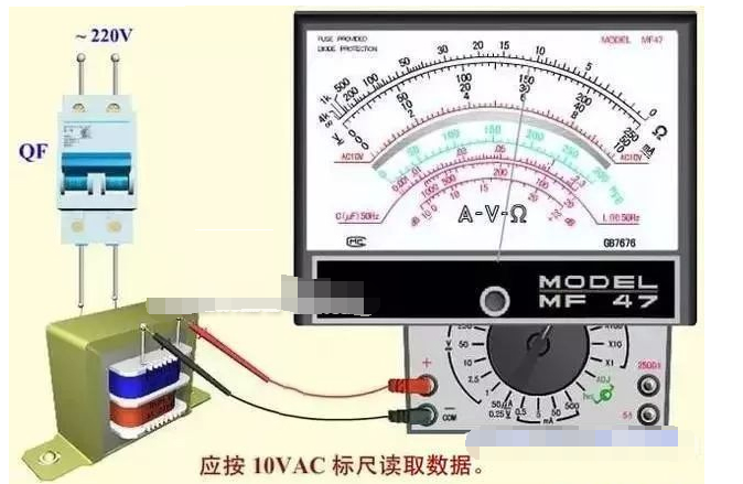
Set the multimeter to AC 400V or higher (higher than 230V will be fine), and measure the voltage between the live wire and the ground. If the voltage is lower than 220V, it means that there is a leakage between the live wire and the ground wire. If you are still worried, measure the voltage between the neutral wire and the ground. Generally speaking, if the three-phase imbalance is not large, the neutral wire and the ground wire have the same potential, and there is no voltage between them, which should be 0V. However, in the case of a live wire leakage, the measured voltage must be around 180V. Therefore, if there is a leakage between the live wire and the ground wire, the live wire leakage is relatively large, and generally the leakage protection cannot be activated.
If the neutral line is leaking to the ground, disconnect all loads, push on the leakage protector, the neutral line current is zero, even if it touches the ground, it is difficult to trip the leakage protector. In this case, the tripping usually occurs only after the electrical appliances are used. The current passes through the loop to make the neutral line energized, and then connected to the ground. If the current exceeds 30ma, the leakage protector will inevitably trip.
The above is a ground fault
If there is a short circuit, it means that the live wire and the neutral wire touch each other without passing through the electrical appliances, or the live wire leaks to the ground and the neutral wire also leaks to the ground. In this case, the air switch at home will directly trip and cannot be closed. Then there is no power under the circuit breaker. Use the multimeter resistance block to measure the live wire and the neutral wire. If there is resistance, it means a short circuit. If there is no resistance, it means that there are too many electrical appliances and the overload protection circuit breaker trips, or the contact resistance caused by the virtual connection of the wire ends is too large to cause overheating and overload protection.

2. Operation without power supply
Set the multimeter to the resistance range, and measure the lower end of the circuit breaker to be tested. Use the red and black test leads to directly measure the live wire to ground and the neutral wire to ground. If there is a buzzer or resistance value, it means that the live wire and the neutral wire are leaking to the ground. If there is resistance between the live wire and the neutral wire, it means a short circuit! The best way is to use a megohmmeter to measure the insulation between the phases and the ground, provided that the load and the main switch are disconnected, because some slight leakage or moisture cannot be detected by the multimeter, and it is difficult to check if the power trips at irregular intervals.
- How to test whether the multimeter is working properly
- New function added to MF-47D multimeter - infrared remote control detection
- Detection of Bidirectional Trigger Diode
- Temperature-frequency conversion circuit composed of CD4046
- Homemade Metal Detector
- How to use STM32 to design an alcohol tester
- How to create a simple oscilloscope using the Basys3 board
- 1.5V and 9V battery tester circuit diagram
- Electric vehicle luminous voltmeter with undervoltage alarm
- A simple no-load self-stop circuit for welding machines
- Overcurrent detection circuit
- Multimeter AC voltage measurement circuit
- Bus door status detection circuit
- Wiring of lightning protection belts, voltage equalizing rings, etc. in high-rise buildings
- How to connect NCS system protection to zero (when cables are introduced)
- M9700 digital multimeter circuit
- MF-500 multimeter circuit
- Applications to change output voltage polarity (b)
- General form of differential input
- Multimeter AC/DC automatic conversion circuit diagram


 京公网安备 11010802033920号