Analysis of the working principle of LM317 voltage regulator circuit
Source: InternetPublisher:常思一二 Keywords: lm317 voltage regulator circuit three-terminal voltage regulator Updated: 2024/07/17
LM317 is one of the most widely used power integrated circuits. It not only has the simplest form of a fixed three-terminal voltage regulator circuit, but also has the characteristics of adjustable output voltage. In addition, it also has the advantages of wide voltage regulation range, good voltage regulation performance, low noise, and high ripple suppression ratio. LM317 is an adjustable 3-terminal positive voltage regulator that can provide more than 1.5A of current in the output voltage range of 1.2V to 37V. This regulator is very easy to use.
The LM317 is suitable for a variety of applications, including local, card regulation. The device can also be used to make a programmable output regulator, or by connecting a fixed resistor between the regulation and the output, the LM317 can be used as a precision current regulator. The working principle of the LM317 voltage regulator circuit is based on the principle of feedback circuit, which controls the change of input voltage by adjusting the output voltage, thereby achieving a stable output voltage.
LM317 internal schematic diagram

LM317 voltage regulator circuit diagram (I)
The following is a typical positive voltage regulator circuit using LM317:

As shown above, it is a classic voltage regulator circuit using LM317. The input voltage is fed to pin 3 (Vin) of the IC and the regulated output voltage is available from pin 2 (Vout) of the IC. The resistor network consisting of R1 and R2 is connected to pin 1 (adj) to set the output voltage. C1 is the input filter capacitor while C2 is the output filter capacitor. The output voltage of the voltage regulator circuit depends on the formula, Vout=1.25V(1+(R2/R1))+IadjR2.
LM317 voltage regulator circuit diagram (II)
The following is an adjustable voltage regulator circuit with digitally selected output:

As shown above, a very simple adjustable voltage regulator circuit with digitally selected output. The circuit is just a modification of a normal voltage regulator using LM317. In parallel with resistor R4, four more resistor branches are added, each with a transistor switch, and these resistors can be included or excluded from the circuit by turning the corresponding switching transistor ON. In simple terms, the output voltage will be based on the logic level of the digital inputs A, B, C, and D. The logic high level at terminal A will turn on Q1, so resistor R5 will be connected in parallel to R4, and so on. Connecting each resistor in parallel to R4 will reduce the effective resistance of the path, so the output voltage of the resistor will be reduced in steps. The width of each step depends on the value of the selected resistor. Resistor R4 sets the maximum output voltage, according to the formula VoutMax=1.25V(1+(R4/R3))+(IadjxR4).
LM317 voltage regulator circuit diagram (III)
The following is a power follower circuit using LM317:
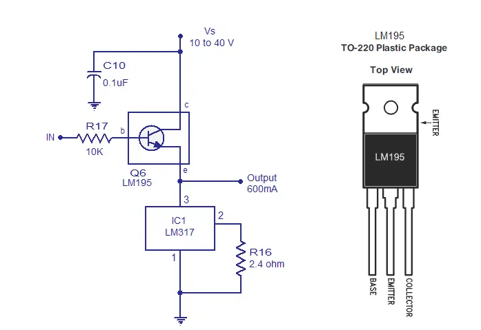
A voltage follower circuit is a circuit that produces considerable current gain while the voltage gain remains at unity (or close to unity). A power follower is nothing but a voltage follower with high current capability. A typical voltage follower circuit designed using small signal transistors can handle a few hundred milliamps of current. The power follower circuit shown below can handle up to 600mA of output current. The circuit shown below is nothing but an emitter follower circuit using a power transistor LM195 (Q6) with a LM317 based current limiter circuit connected at the emitter. In simple terms, the current limiting circuit replaces the “emitter resistor” of the classic transistor emitter follower. Capacitor C10 is the input filter. The LM195 is a monolithic power transistor with full overload protection.

- Build a simple buck-boost regulator and test it on a breadboard
- Using Lead-acid Battery as Power Source for Walkman
- Fabrication of multi-cell lithium battery charging circuit
- MT3608 constitutes a 3.7V to 12V boost circuit diagram
- Constant current LED lamp driver circuit with soft start and anti-shock
- LNK304 non-isolated LED light string driver circuit
- A small and easy-to-make fast charger
- Homemade low-power UPS
- USB power socket using the car battery
- Car Audio Power Supply
- STR5412 power circuit
- 24V power supply pure flat display high voltage power supply circuit diagram
- Portable device charging power circuit design
- Photoelectric control digital tube display circuit
- 4-phase CPU power circuit using HIP6301 and HIP6602 chips
- Single phase thyristor slotless nickel plated power circuit
- 300A-18V three-phase thyristor voltage regulating electrolytic power supply circuit
- Practical regulated power supply circuit diagram using LM317
- Low dropout three-terminal voltage regulator MC33269 circuit diagram
- Low dropout three-terminal voltage regulator MC33269 circuit diagram


 京公网安备 11010802033920号