1 Introduction
The DC resistance test of transformer windings is one of the main items of transformer factory and preventive testing. According to the IEC standard and the national standard GB1094, this test must be carried out on the transformer during the manufacturing process, after overhaul, handover test and preventive test, as well as the measurement of the average temperature rise of the winding and fault diagnosis [1].
In recent years, the testing methods of DC resistance of power transformers have been discussed in detail in references [2~4]. These methods can be divided into two main categories: static and dynamic measurement methods. The so-called static measurement method refers to the measurement after the winding charging current is stable. It includes the circuit mutation method to increase the loop resistance, the high-voltage charging and low-voltage measurement method, the magnetic flux pump method, etc. They all have the disadvantage that the measurement process must rely on manual intervention. . The so-called dynamic measurement method means that you do not need to wait until it is stable before measuring, but use the voltage and current data during the charging process of the inductor coil to measure its resistance. Among the dynamic measurement methods, the second-order oscillation method has higher requirements for the capacitance connected in series in the loop, and also requires strict control of the current extreme point. If di/dt≠0, and the value of the inductance is large, the resulting The inductor voltage drop UL = Lx (di/dt) is superimposed on the very small voltage drop UR of the DC resistance, which reduces the measurement accuracy. Generally speaking, the static measurement method takes a long time, but the measurement data is relatively reliable; the dynamic measurement method is fast and efficient, but the measurement data is sometimes unreliable.
Based on their respective characteristics, this article proposes the "degaussing dynamic method" with the help of TI (Texas Instrument) company signal processor (DSP), striving to integrate the advantages of the two methods to solve the problem of intelligent, fast and reliable measurement of large-scale power The problem of equipment DC resistance, especially the rapid measurement of large-capacity three-phase five-post transformers.
2 Analysis of the principle of the test system
2.1 Basic idea of the degaussing method
The conventional method of studying three-phase three-column transformers is to equate the power transformer winding to the series connection of inductance and resistance. The change process of the winding current is:
 |
Among them, τ=Lx/Rx is the loop time constant; Rx and Lx are the DC resistance and inductance of the transformer winding under test; E and i are the power supply and loop current.
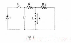
The circuit transition process of the mutual inductance coupling winding of the three-phase five-column transformer is briefly analyzed below. The equivalent circuit is shown in Figure 1. Among them, R1 is the primary resistance; R2 is the converted value of the secondary resistance; L is the inductance corresponding to the magnetizing reactance. The impedance function of this circuit is:
  |
The forced response (i.e., the steady-state component of the terminal voltage) and natural response of this circuit are:
 |
The full response of the circuit is the sum of the forced response and the natural response, that is,
 |
The undetermined constant A can be obtained from the initial conditions. Therefore, the time variation function of the terminal voltage is
 |
Then, if a constant current source is passed into a transformer with a short-circuited secondary side, although the primary side current quickly reaches its stable value, due to the influence of the secondary side induced inductor current, it will take a long time for the primary side voltage to reach its stable value. stable value. It can be seen that the transition process of the mutual inductance coupling winding circuit is determined by the secondary parameters and has nothing to do with the primary. Even increasing the internal resistance of the power supply does not affect the secondary time constant.
The reason why there is a transition process in the inductive winding after power is applied is that the magnetic flux cannot mutate. Transition time is required when converting from one stable state to another. If the residual magnetism is omitted, when measuring the DC resistance of the transformer, its initial state magnetic flux is zero. If we manage to maintain this zero state throughout the measurement process, the transition process is fundamentally eliminated and the purpose of rapid measurement is achieved.
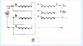
While measuring the DC resistance of the high (medium) voltage coil, add reverse current to the medium (low) voltage coil in order to offset the current magnetic field. That is to say, when measuring the DC resistance of the high-voltage side, in addition to adding current to the high-voltage phase coil to be measured, a reverse current should also be added to the corresponding medium-voltage side coil so that the magnetic potential generated by this current is consistent with the high-voltage side coil. The generated magnetic potentials are equal in magnitude and opposite in direction. If they can be added at the same time, the performance will cancel each other out. That is, it is guaranteed to maintain the "zero magnetic flux" state during the entire measurement process. The simplified diagram is shown in Figure 2 (low voltage winding omitted).
  |
Suppose there are N1 turns on the high-voltage side and N2 turns on the medium-voltage side, then the magnetic potential on the high-voltage side is N1i1 and the medium-voltage side is N2i2. For example, N1i1+N2i2=0, then i2=-N1·i1/N2, because N1/N2=u1/ u2, therefore, the turns ratio can be obtained from a certain tap voltage ratio given on the nameplate.
When measuring the low-voltage side winding, the simplified circuit is shown in Figure 3. It can be seen from the figure that the medium- and low-voltage turns ratio is the ratio of the medium-voltage line voltage and the low-voltage line voltage. If the medium-voltage line voltage is u2 and the low voltage is u3, then N2/N3 = (u2//  u3. And because the low-voltage winding system Phase bc is connected in series and connected in parallel with phase a. Therefore, the total injected current should be 1.5 times the current of phase a, that is,
 |
Satisfying the relationship (8) can make the medium and low voltage magnetic potentials cancel each other out. The DSP is used to control the size of the degaussing current output by the constant current source to complete the test.
2.2 The basic idea of dynamic testing method
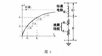
The "static" method alone cannot well solve the contradiction between the accuracy and rapidity of measurement. To this end, this article proposes a "dynamic" testing method based on the "static" measurement idea. The schematic diagram of the principle is shown in Figure 4. In the figure, UN is the upper end voltage of the high-precision standard resistor RN that is connected in series to the winding, and E is the terminal voltage of the winding under test.
 |
It can be seen from equation (1) that during the demagnetization process, the UN and E values at two different times, t1 and t2, can be measured. Substituting them into equation (1), we can get:
 |
Theoretically, the smaller the value of Δt, the more accurate the direct resistance value RX solved by equations (9) and (10), so ensuring the accuracy of the measurement is not a problem, but this is not the case. When Δt is small to a certain extent, the error in the calculated RX value will increase as Δt decreases. This is because factors such as the word length in computer operations, the quantization error during A/D conversion of analog signals, and the natural time constant of the coil all have an impact on the calculation results of direct resistance RX. Dynamic testing methods must undergo careful research and a large number of simulation tests to arrive at the optimal measurement plan. However, after passing the degaussing current during the measurement process, the change of the current is relatively stable (that is, Δi is small), and the number of sampling points can be smaller. Therefore, the value of Δt can be relatively larger, which reduces the workload of the microprocessor. computational burden. This tester determines the number of sampling points according to the following formula:
 |
In equation (11), Δi and δ are set by the computer in advance. The voltage is continuously sampled within the Δt (set by the computer in advance) time interval, and judgment is made. Once the requirements are met, there is no need to sample the voltage, but data processing is performed to complete functions such as display and PC communication.
3 Test system introduction
The entire test system uses TMS320F240 as the control center. The system block diagram is shown in Figure 5. TMS320F240 (16-bit fixed-point processor) integrates high-performance DSP core and rich microcontroller peripheral functions into a single chip, making it ideal for traditional multi-microprocessor units (MCU) and expensive multi-chip designs. Substitutes [5]. F240 has 16 channels of 10bit A/D input interface. Due to its excellent performance, a single chip can basically complete all functions of the system. Compared with conventional designs, the use of F240 chip makes the system hardware circuit simple, reduced in size, and software Programming also becomes easier. In order to realize the function of this system, the F240 external 64Kbyte data storage unit is used for data calculation, processing and storage; the MAX715 chip is used to provide various voltages required by the system; the power monitoring chip MAX691 ensures the normal supply of power, write protection of RAM and system Low-voltage detection function; the communication interface uses the MAX232 chip; the REF02 precision voltage/temperature sensor chip is selected, which can measure the ambient temperature at the same time; the user interface is equipped with a 192×128 dot matrix LCD display and a 4×4 keyboard to facilitate parameter display and user control A variety of functional operations; data collection, transition edge capture, "watchdog", program storage, etc. are all implemented by F240. Before testing, clamp all test clamps to the transformer terminals and switch the measuring terminals under computer control.
 |
4 Measurement tasks
4.1 Calculate the unbalance rate of phase-to-phase resistance and line-to-line resistance [4]
In the GB6451-86 "Technical Parameters and Requirements for Three-Phase Immersed Power Transformers" series of standards, the unbalance rate of three-phase winding DC resistance is stipulated limit value. When the capacity is 1600kVA, the phase resistance unbalance rate is required to be ≤±4% and the line resistance unbalance rate is ≤±2%; when the capacity is larger, the phase resistance unbalance rate (when the neutral point is drawn out) and the line resistance are not The balance rate is ≤2%. Therefore, the corresponding resistance unbalance rate must be calculated based on the measurement results.
4.1.1 Phase and line resistance unbalance rate expressions
Assume the resistance values of the three phase windings of the three-phase transformer are Ra, Rb and Rc respectively; let the maximum phase winding and the minimum phase winding be Rmaxp and Rminp respectively. Therefore, according to the definition of phase resistance unbalance rate Sp, there is:
 |
It is also assumed that the line resistance between any two terminals of the three terminals a, b and c of the three-phase transformer is expressed as Rab, Rbc and Rca respectively, and it is assumed that Rmaxl is the maximum and Rminl is the minimum. Therefore, the definition of line resistance unbalance rate Sl is:
 |
4.1.2 The expression of line resistance unbalance rate when Y or Z connection is used.
From the perspective of measuring the current resistance using a DC power supply, there is no difference between Y connection and Z connection. They both have:
Rab=Ra+Rb,
Rbc=Rb+Rc,
Rca= Rc+Ra.
When Ra is the largest and Rc is the smallest, Rab is the largest and Rbc is the smallest. Then equation (13) is transformed into:
 |
It can be seen from equation (14) that the line resistance unbalance rate S1 in Y connection and Z connection is always equal to half of the phase resistance unbalance rate Sp.
4.1.3 Calculation of the unbalanced rate of line resistance in D connection
. In D connection, the line resistance measured each time is composed of two phase windings connected in series and then in parallel with the third phase winding. Assume that Ra is the largest and Rc is the smallest. Therefore, the line resistance unbalance rate Sl is:
 |
4.2 Conversion of winding DC resistance value R75
The resistance of the transformer winding is affected by temperature. When measuring, the ambient temperature at that time should be recorded (it is best to measure the winding temperature). For transformers without oil immersion, use room temperature as the test temperature. If it has been immersed in oil, use the oil surface temperature as the test temperature. If the winding temperature is much higher than room temperature after the transformer is in operation, it is best to wait until the temperature drops to a stable level before measuring. For R75 conversion method, please refer to relevant information, which is omitted here.
 |
5 Test results and credibility analysis
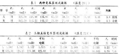
A in Table 1 represents a scrapped three-phase transformer (capacity: 1250kVA, connection group: Y0/Δ), B represents a 1250kVA three-phase transformer (connection group: Y0 /Δ), H represents the high-end DC resistance. Table 2 shows a giant three-phase five-column transformer in a factory: capacity 240MVA, voltage 242/15.75kV, connection group: Y0/Δ, where L represents the low-end DC resistance and H represents the high-end DC resistance. Observing the measurement data, it can be seen that their differences belong to normal distribution, the data is credible [6,7], and the measurement time is short and the efficiency is high. It can be seen from SP and SL in Table 1: A is scrapped and B is normal. It can be seen from Table 2 that the SP and SL of the transformer have exceeded 2%, and the fault should be checked and eliminated in time.
6 Conclusion
The characteristic of this method is that it reasonably organically unifies static and dynamic testing methods. It is especially suitable for the winding DC resistance of power transformers with different capacities, different connection groups, and five- or three-column cores. Fast, accurate and reliable measurement; another feature of this method is the reasonable selection of DSP digital processor, which can process data quickly and accurately; because it is powered by batteries, there is no need to add new equipment, and this method is extremely easy Implemented on site.
Previous article:"Degaussing Dynamic" Method Test of Transformer DC Resistance Based on DSP
Next article:Image compression system based on TMS320C5409
- Popular Resources
- Popular amplifiers
-
 Introduction to Transformer Natural Language Processing: Solving Problems with Hugging Face Libraries and Models
 -
 CVPR 2023 Paper Summary: Vision Applications and Systems
 -
 CVPR 2023 Paper Summary: Video: Low-Level Analysis, Motion, and Tracking
 -
 CVPR 2023 Paper Summary: Photogrammetry and Remote Sensing
- Huawei's Strategic Department Director Gai Gang: The cumulative installed base of open source Euler operating system exceeds 10 million sets
- Analysis of the application of several common contact parts in high-voltage connectors of new energy vehicles
- Wiring harness durability test and contact voltage drop test method
- Sn-doped CuO nanostructure-based ethanol gas sensor for real-time drunk driving detection in vehicles
- Design considerations for automotive battery wiring harness
- Do you know all the various motors commonly used in automotive electronics?
- What are the functions of the Internet of Vehicles? What are the uses and benefits of the Internet of Vehicles?
- Power Inverter - A critical safety system for electric vehicles
- Analysis of the information security mechanism of AUTOSAR, the automotive embedded software framework
 Professor at Beihang University, dedicated to promoting microcontrollers and embedded systems for over 20 years.
- Innolux's intelligent steer-by-wire solution makes cars smarter and safer
- 8051 MCU - Parity Check
- How to efficiently balance the sensitivity of tactile sensing interfaces
- What should I do if the servo motor shakes? What causes the servo motor to shake quickly?
- 【Brushless Motor】Analysis of three-phase BLDC motor and sharing of two popular development boards
- Midea Industrial Technology's subsidiaries Clou Electronics and Hekang New Energy jointly appeared at the Munich Battery Energy Storage Exhibition and Solar Energy Exhibition
- Guoxin Sichen | Application of ferroelectric memory PB85RS2MC in power battery management, with a capacity of 2M
- Analysis of common faults of frequency converter
- In a head-on competition with Qualcomm, what kind of cockpit products has Intel come up with?
- Dalian Rongke's all-vanadium liquid flow battery energy storage equipment industrialization project has entered the sprint stage before production
- Allegro MicroSystems Introduces Advanced Magnetic and Inductive Position Sensing Solutions at Electronica 2024
- Car key in the left hand, liveness detection radar in the right hand, UWB is imperative for cars!
- After a decade of rapid development, domestic CIS has entered the market
- Aegis Dagger Battery + Thor EM-i Super Hybrid, Geely New Energy has thrown out two "king bombs"
- A brief discussion on functional safety - fault, error, and failure
- In the smart car 2.0 cycle, these core industry chains are facing major opportunities!
- The United States and Japan are developing new batteries. CATL faces challenges? How should China's new energy battery industry respond?
- Murata launches high-precision 6-axis inertial sensor for automobiles
- Ford patents pre-charge alarm to help save costs and respond to emergencies
- New real-time microcontroller system from Texas Instruments enables smarter processing in automotive and industrial applications
- STEVAL-MKSBOX1V1 (SensorTile.box) firmware download via USB
- HP Prime G2 calculator with MicroPython support
- STM32 output 4-20MA or 0-10V circuit sharing
- LIS2MDL array PCB engineering and code information for magnetic nail navigation AGV car
- Live Review: Rochester Electronics Semiconductor Full-Cycle Solutions (including videos, materials, Q&A)
- How to understand this parameter in the MOS tube specification?
- Why is it necessary to use a four-pin Kelvin connected resistor for current detection?
- Purgatory Legend-12864 LCD War
- Live Review: How to Design High-Performance Servo Drives Using Infineon IGBT7
- [Raspberry Pi 4B Review] + ARIA2 Remote Download Server Construction

 Introduction to Transformer Natural Language Processing: Solving Problems with Hugging Face Libraries and Models
 CVPR 2023 Paper Summary: Vision Applications and Systems


 京公网安备 11010802033920号