The concept of intelligent transportation system (ITS) was proposed by the American Intelligent Transportation Society in 1990. It comprehensively applies advanced information technology, communication technology, automatic control technology, electronic technology and computer processing technology to the entire transportation management system. Collect, transmit and process traffic information, coordinate and manage transportation, and establish a real-time, accurate, and efficient comprehensive transportation management system, thereby improving transportation efficiency and safety, and realizing intelligent transportation services and management. .
Research on key technologies of intelligent transportation systems such as navigation and positioning of intelligent vehicles, automatic driving and control, and vehicle early warning and collision avoidance have received more and more widespread attention at home and abroad in recent years, and have also achieved fruitful results. However, there are still very few real experimental studies, and basically only simulation experiments have been conducted. In view of the fact that the theoretical simulation and actual application may be far apart, a mobile robot with the advantages of intelligence, easy scalability and mobility was selected as the main part of the research platform for ITS key technologies - the vehicle simulator.
The mobile robot SJTNC-1 described in this article is proposed for ITS. Considering that a large amount of calculations are required in key technology research, such as fuzzy control, Kalman filtering and path guidance, and the system has high requirements for real-time data, a digital signal processor (DSP) is used as the main control of the mobile robot. CPU.
1 Introduction to TMS320LF2407A
TMS320LF2407A (hereinafter referred to as F2407) is designed by TI Company for digital motor control based on the TMS320 series DSP. In addition to the improved Harvard structure, multi-bus structure and pipeline structure of general DSP, it also uses high-performance static CMOS technology, reducing the voltage from 5V to 3.3V, reducing power consumption. And the instruction execution speed is increased to 40MIPS, and almost all instructions can be completed in a single cycle of 25ns. Such a high computing speed enables the performance of the system to be improved by using advanced control algorithms such as fuzzy control, Kalman filtering and state control. Moreover, it has the necessary peripherals for motor control applications, such as: 32K on-chip FLASH, 2K single-access RAM, serial peripheral interface (SPI), serial communication interface (SCI), two event management modules, 16 channels Dual 10-bit A/D converter and CAN controller module.
2. The motion mechanism of the mobile robot
. Considering that the mobile robot is oriented to ITS, it adopts a vehicle structure (four-wheel structure). The first two wheels are connected to the steering motor through a gear reduction mechanism with a reduction ratio of 8:1 to realize the steering function of the mobile robot; the rear two wheels are connected to the drive motor through a gear reduction mechanism with a reduction ratio of 6:1 to realize the mobile robot of drive. The motor selection can be a small stepper motor or a small DC motor according to the actual situation. The DC motor produced by the Swiss Minimotor company is used here. This motor has the characteristics of small size and large torque.
3 Mobile robot control system
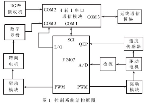
The control system takes the controller F2407 as the core and consists of wireless communication, motor drive, speed sensor, digital compass, differential GPS (DGPS) receiver and 4-to-1 serial communication module, as shown in Figure 1. The wireless communication module receives the planned path information from the host computer according to the self-agreed communication protocol, and the entire control system controls the drive motor and steering motor to enable the mobile robot to track the path. The motor adopts PWM speed regulation, in which the drive motor adopts a double closed-loop (speed and current) PID control strategy, while the steering motor uses the heading information of the digital compass as the feedback amount of the steering for PID control. The entire control system uses the position information of the DGPS receiver as the position feedback information of the system to complete the position closed-loop control of the entire system.

3.1 Wireless communication module
MC35 is a dual-band GSM module produced by Siemens of Germany that can be developed for secondary development and supports GPRS. It can be connected to a PC through a standard serial port. This system uses MC35 as the communication module between the mobile robot and the host computer. It has all the advantages brought by GPRS technology, such as always online and providing high-speed and low-cost data transmission services. The characteristics of this product are as follows:
·Supports dual-band: EGSM900/GSM1800
·Supports GPRS Class8 protocol
·Supports data, voice, short message and fax services
·Adopts circuit switching mode, the maximum transmission rate is 14.4kbps
·Supported voltage range: 8V~ 30V
·Using standard industrial interface
·Volume: 65mm×74mm×33mm
·Weight: 130g
3.2 Drive module
The drive motor and steering motor have the same driving principle, and both use pulse width modulation (PWM) for speed regulation. The PWM signal is generated by F2407. The driving circuit adopts H full-bridge mode and consists of 4 Darlington tubes (2 TIP132 and 2 TIP137), 4 IN4001 diodes and NAND gates. The circuit schematic is shown in Figure 2. When PWM2 and PWM4 are low level and PWM1 and PWM3 are high level, T1 and T4 are saturated and turned on, T2 and T3 are cut off, the current changes from T1 → motor → T4, and the motor rotates forward; conversely, when PWM1 and PWM3 are low power When PWM2 and PWM4 are at high level, T2 and T3 are saturated and turned on, T1 and T4 are cut off, the current changes from T2→motor→T3, and the motor reverses.

In order to prevent T1, T3 or T2, T4 from being turned on at the same time, forming a short circuit and breaking down the device, a pair of non-overlapping PWM outputs must be used to correctly turn on and off the two pairs of tubes. Add a dead time between one tube turning off and the other tube turning on, so that before one tube turns on, the other tube is completely turned off. A major feature of the F2407 is that it has a dead zone control unit, so that software can be used to ensure that the turn-on intervals of the upper and lower bridge arm switching elements of the power circuit do not overlap, simplifying the hardware circuit design and improving reliability.
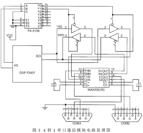
3.3 4 to 1 serial port communication module Since the DGPS receiver, magnetic compass, odometer and MC35 communication module all use RS-232 asynchronous serial communication, and the F2407 has only one serial port, the 4 serial port data must be converted and processed. Complete the serial communication with F2407. For this purpose, a 4-to-1 serial port communication module based on time-division multiplexing method was developed. When F2407 needs data from a certain sensor (or wireless communication module), it will strobe the sensor through the circuit and occupy the F2407 serial port for communication; when it needs data from another sensor or wireless communication module, it will turn off the strobe of the previous sensor. At the same time, the secondary sensor or wireless communication module is selected. The 4-to-1 serial communication module is composed of a 3-8 decoder 74LS138, a three-state output four-bus buffer gate 74LS125, and a level converter MAX232. Its circuit schematic is shown in Figure 3.

3.4 Positioning Sensor
3.4.1 DGPS Receiver
GPS (Global Positioning System) is a satellite-based radio navigation system that provides a cheap and practical tool for determining position, speed and time on a global scale. GPS consists of 24 satellites (21 operating satellites and 3 backup satellites). The constellation is distributed on 6 orbital planes with an inclination of 55° to the earth's equatorial plane. Its operating period is 11 hours and 58 minutes, and the orbit radius is 20,200km. , the angle between each track surface is 60°. Each satellite emits L-band ultra-high continuous waves to the earth, modulating two pseudo-random codes (military high-precision confidential P code and civilian C/A code). Such distribution characteristics ensure that users can continuously receive navigation signals from at least four satellites at any time and anywhere on the earth, thereby simultaneously calculating the three-dimensional coordinates of the receiver and the time offset between the receiver and GPS. The three-dimensional coordinates adopt the ECEF Cartesian coordinate system or the geodetic coordinate system such as WGS84.
Although the U.S. government canceled the optional protection of civilian C/A codes in May 2001, the single-point real-time positioning accuracy of civilian navigation GPS receivers can only reach about 25m, which cannot meet the positioning and navigation requirements of the system. Using real-time differential GPS (DGPS), the positioning accuracy can reach 2 to 5m, which can meet the requirements of system positioning and navigation.
For this purpose, a single base station DGPS (SRDGPS) system was developed, and its structural block diagram is shown in Figure 4. The base station is composed of ALLSTAR BASE GPS receiver, antenna and MDS radio transmitter and antenna, and the rover is composed of SUPERSTAR GPS receiver, antenna and MDX radio receiver and antenna. The base station is installed on the roof of the first floor of the teaching building of Xujiahui Campus of Shanghai Jiao Tong University. The base station can cover a radius of 30 kilometers, and the rover is installed on the vehicle-mounted unit.

3.4.2 Digital compass and vehicle speed sensor
HoneyWell’s HMR 3300 digital compass is used as the direction detection sensor of the mobile robot. Its main technical indicators are: (1) 1 degree heading accuracy, 0.1 degree resolution; (2) 0.5 degree repeatability; (3) ±60 degree tilt and pitch range; (4) 15Hz response time; (5) -40± 85 degree operating temperature; (6) 6~15V DC voltage.
At the same time, the Hall speed sensor used in Volkswagen Santana 2000 sedan is used as the speed sensor of the mobile robot. Its working principle is to use the Hall sensor as a conversion element to convert the mechanical rotation amount into an electrical pulse signal output. The main technical indicators are: (1) The output waveform is a rectangular pulse with a duty cycle of 50%; (2) 6 pulses are generated per rotation; (3) The rated voltage is 12V.
4 Power module
The power module needs to supply power to each sensor, DSP chip, other chips and motors respectively. Among them, the magnetic compass, code disk and DGPS receiver use 12V DC voltage, the DSP chip uses 3.3V DC voltage, other chips use 5V DC voltage, and the motor power supply uses 12V DC voltage. Therefore, a 12V DC battery (4AH) is used, the DC 5V is realized through L7805 of ST Semiconductor Company and the power tube for current expansion, and the 3.3V power supply of the DSP chip is realized by 1SMB5913BT3 of ON Semiconductor Company. When F2407 is working normally, all power supply pins are 3.3V; when writing to FLASH memory, the VCCP pin is powered by 5V; during reset, the reset circuit will generate a continuous low level of 10μs width to reset the chip.
5 Controller program structure
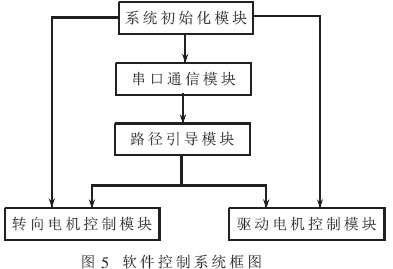
The DSP program consists of five functional modules, namely system initialization module, serial communication module, path guidance module, drive motor control module and steering motor control module. TI provides CC and CCS platforms for C language development. The platform includes an ANSI C optimizing compiler, allowing development and debugging at the source program level. This method greatly improves the development speed and readability of software, and facilitates software modification and transplantation. But in some cases, the efficiency of the code still cannot be compared with the efficiency of hand-written assembly code. In addition, using C language to implement certain hardware controls of the chip is not as convenient as assembly programs, and some cannot even be implemented in language. In order to make full use of the chip's resources and better utilize the respective advantages of C language and assembly language for software development, a hybrid programming method is used to organically combine the two, taking into account the advantages of both and avoiding their disadvantages. The framework of the system is shown in Figure 5. The key modules are briefly described below.

5.1 Serial communication module
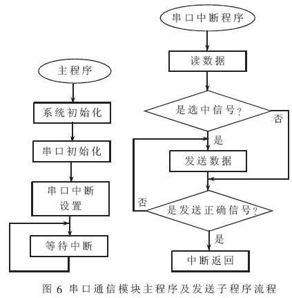
This module program is implemented using serial port interrupts. The main program mainly consists of system initialization, serial port initialization, serial port interrupt setting and waiting for interrupts. The interrupt subroutine is divided into sending subroutine and receiving subroutine. This article gives the flow chart of the sending subroutine. The flow chart of the main program and sending subroutine is shown in Figure 6.

5.2 Path guidance module
This module provides real-time speed and steering instructions to the mobile robot while it is driving, thereby guiding it to travel along the path given by the host computer. It mainly includes the generation of driving instructions and the tracking of planned paths.
According to the preview following theory and the driver's driving behavior characteristics, intelligent driving and driver control behavior are internally consistent. By studying the driver's manipulation behavior, it was found that the forward speed of the vehicle is mainly determined by two factors. These two factors are the curvature of the road and the directional deviation of the robot relative to the reference path.
The control of the forward speed of the mobile robot does not require continuous changes and can be set to three gears, corresponding to high, medium and low speeds respectively. The thus determined forward speed tracking rules are:
·When the direction deviation is less than 10 degrees, the path is basically a straight line, and the forward speed is set to high speed;
·When the directional deviation is less than 90 degrees, the path is severely curved, and the forward speed is set to low speed;
·In other cases, the forward speed is medium speed.
5.3 Drive motor and steering motor control module
The drive motor module adopts a PID control strategy and uses the signal detected by the vehicle speed sensor as the feedback signal of the motor for PID control, achieving good control results. The control strategy of the steering control module is similar to that of the drive motor, except that its feedback signal is the direction signal of the digital compass. The PID control formula is:

In the formula, u(k) is the output of the control; e(k) is the deviation at time k; Kp, Ki, and Kd are the proportional coefficient, integral constant, and differential constant of the PID control algorithm respectively.
References
1 Shi Xinhong. Development of intelligent transportation systems. Journal of Northern Jiaotong University, 2002;26(1):29~34
2 Li Xianyong. Visual C++ serial communication technology and engineering practice. Beijing: People's Posts and Telecommunications Press, 2002
3 Liu Heping.TMS320LF240X DSP structure, principle and application. Beijing: Beihang University Press, 2002
4 Huang Yingzhe. TMS320C240 principle and C language control application practice. Beijing: China Water Conservancy and Hydropower Press, 2003
5 Li Qingzhong. Intelligent preview control of mobile robot path tracking Method Research. Robot, 2002;24(3):252~255
Previous article:Design and implementation of mobile robot based on DSP
Next article:Application of TMC2310 DSP in underwater target detection and parameter estimation
- Huawei's Strategic Department Director Gai Gang: The cumulative installed base of open source Euler operating system exceeds 10 million sets
- Analysis of the application of several common contact parts in high-voltage connectors of new energy vehicles
- Wiring harness durability test and contact voltage drop test method
- Sn-doped CuO nanostructure-based ethanol gas sensor for real-time drunk driving detection in vehicles
- Design considerations for automotive battery wiring harness
- Do you know all the various motors commonly used in automotive electronics?
- What are the functions of the Internet of Vehicles? What are the uses and benefits of the Internet of Vehicles?
- Power Inverter - A critical safety system for electric vehicles
- Analysis of the information security mechanism of AUTOSAR, the automotive embedded software framework
 Professor at Beihang University, dedicated to promoting microcontrollers and embedded systems for over 20 years.
- Innolux's intelligent steer-by-wire solution makes cars smarter and safer
- 8051 MCU - Parity Check
- How to efficiently balance the sensitivity of tactile sensing interfaces
- What should I do if the servo motor shakes? What causes the servo motor to shake quickly?
- 【Brushless Motor】Analysis of three-phase BLDC motor and sharing of two popular development boards
- Midea Industrial Technology's subsidiaries Clou Electronics and Hekang New Energy jointly appeared at the Munich Battery Energy Storage Exhibition and Solar Energy Exhibition
- Guoxin Sichen | Application of ferroelectric memory PB85RS2MC in power battery management, with a capacity of 2M
- Analysis of common faults of frequency converter
- In a head-on competition with Qualcomm, what kind of cockpit products has Intel come up with?
- Dalian Rongke's all-vanadium liquid flow battery energy storage equipment industrialization project has entered the sprint stage before production
- Allegro MicroSystems Introduces Advanced Magnetic and Inductive Position Sensing Solutions at Electronica 2024
- Car key in the left hand, liveness detection radar in the right hand, UWB is imperative for cars!
- After a decade of rapid development, domestic CIS has entered the market
- Aegis Dagger Battery + Thor EM-i Super Hybrid, Geely New Energy has thrown out two "king bombs"
- A brief discussion on functional safety - fault, error, and failure
- In the smart car 2.0 cycle, these core industry chains are facing major opportunities!
- Rambus Launches Industry's First HBM 4 Controller IP: What Are the Technical Details Behind It?
- The United States and Japan are developing new batteries. CATL faces challenges? How should China's new energy battery industry respond?
- Murata launches high-precision 6-axis inertial sensor for automobiles
- Ford patents pre-charge alarm to help save costs and respond to emergencies
- Inverter air conditioner outdoor unit control system based on Zhongying SH32F205
- Common Verilog Syntax for FPGA Design
- The interfaces of LED unit boards are all HUB75E, so they cannot be used interchangeably by different brands?
- About Full Wave Analysis
- The up-counting mode of Timer A of MSP430 is not written with new period = old period, what will happen to the counter?
- ADI ADUM7702 16-bit isolated Sigma-Delta 24-bit AD7793+ADU5401 isolator data
- DSP F2812 Interrupt
- Problems with the Arteli AT-LINK-EZ virtual serial port
- Which one is better to learn, microcontroller or DSP?
- How to prevent PCB warping

 Digilent Vivado library
 Motor Control and Learning (Markus Latash, Francis Lestienne)
 HslCommunicationDemo host computer debugging software


 京公网安备 11010802033920号