Working Principle of DC Generator
The working principle of a DC generator is as follows:
1. Construction: A DC generator consists of two parts: a stator and a rotor. The stator is made of a set of windings, which are placed around the rotor. The rotor is made of a set of permanent magnets, which rotates through the input of mechanical energy (for example, steam energy, hydraulic energy, wind energy, etc.).
2. Working Principle: When the rotor of a DC generator starts to rotate, the magnetic field travels along the surface of the rotor, interacting with the conductors in the stator windings, causing changes in the magnetic flux.
3. Magnetic flux changes: When the magnetic flux moves along the conductor in the stator winding, a magnetic field is formed due to the current in the conductor, which reacts with the rotor magnetic field to guide the electrons in the conductor to move. In this process, the electrons in the conductor will flow through the wire, generating current. Two Schicken comb brushes are used to collect electrical energy to form a circuit from the stator winding to the load. This is the principle of how a DC generator generates current.
4. Voltage control: In order to stabilize the voltage of the generator, the current and voltage output of the generator can be controlled by adjusting the size of the permanent magnet or adjusting the number and size of the stator windings. In addition, the current and voltage output can be controlled by using a regulator or self-excitation principle.
In short, the working principle of the DC generator is based on the principle of electromagnetic induction caused by magnetic flux changes. By placing the rotor and the stator together, the rotation of the rotor induces current in the stator winding through the change of the magnetic field. This is the basic principle of the DC generator using mechanical energy to convert into electrical energy.
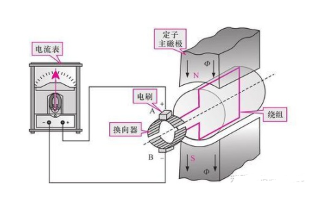
When a DC generator is working, the external mechanical force drives the conductor coil to rotate in the magnetic field and continuously cuts the magnetic flux lines to generate induced electromotive force. The figure shows the working principle of a typical DC generator.

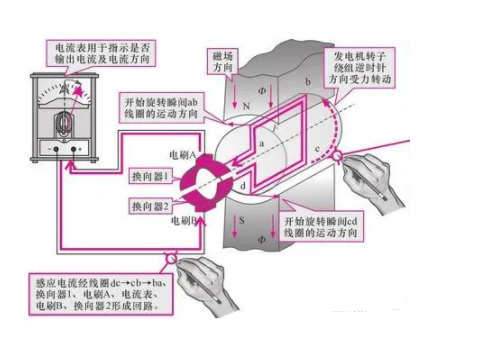
The figure shows the working process of the DC generator rotor winding when it starts to rotate. When the external mechanical force drives the winding to rotate, the coils ab and cd cut the magnetic flux lines respectively. According to the principle of electromagnetic induction, current is generated inside the winding. The direction of the current can be determined by the right-hand rule: the induced current forms a loop through the coil dc→cb→ba, commutator 1, brush A, ammeter, brush B, and commutator 2.

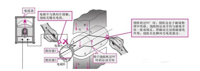
The figure shows the working process of the DC generator rotor winding after it rotates 90°. When the winding rotates 90°, the two winding edges are in the physical neutral plane of the magnetic field, and the brushes are not in contact with the commutator segments, no current flows in the winding, F=0, and the torque disappears.

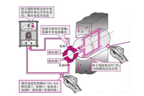
The figure shows the working process of the DC generator rotor winding after it rotates 90°. Under the action of external mechanical force, the rotor winding continues to rotate, and the winding continues to cut the magnetic flux lines, and an induced current can be generated in the winding. The induced current forms a loop through the winding ab→bc→cd, commutator 2, brush A, ammeter, brush B, and commutator 1.

As can be seen from the figure, the induced electromotive force in the rotor winding is an alternating electromotive force, while the electromotive force at the brush AB end is a DC electromotive force. That is, through the commutator and the brushes, the current output by the rotor winding is always in one direction, which is the working principle of the DC generator.
It is worth noting that in actual DC generators, the rotor winding is not a single coil, but is composed of many coils. These coils in the winding are evenly distributed in the slots of the rotor core, and the ends of the coils are connected to the corresponding sliders of the commutator. The commutator is actually composed of many arc-shaped conductive sliders, which are insulated from each other by mica sheets. The more the number of coils and commutator sliders, the smaller the DC pulsation generated by the generator. Generally, the output voltages of small and medium-sized DC generators are 115V, 230V, and 460V, and the output voltage of large DC generators is about 800V.
Difference Between DC Generator and AC Generator
DC generator and AC generator are the two main types of generators and the differences are as follows:
1. Different working principles
The working principle of a DC generator is to achieve electrical energy conversion through the interaction of magnetic lines of force between the armature and the permanent magnet, directly converting mechanical energy into DC power. The AC generator, on the other hand, generates an alternating potential by cutting the magnetic field with a rotating exciter, thereby converting mechanical energy into AC power.
2. Different power generation methods
The power output of a DC generator is direct current, and the output voltage and current are adjustable; while the power output of an AC generator is alternating current, and the output voltage and current are determined by the design parameters of the exciter and the conductor, and are generally fixed.
3. Different maintenance difficulty
The circuit structure of a DC generator set is relatively simple, and the maintenance difficulty is relatively low; however, the design requirements of an AC generator set are relatively strict, and it is more difficult to maintain. At the same time, an adaptive circuit management system is also required to ensure stable output.
4. Different uses
Since its output is direct current, DC generators are often used in applications with relatively high requirements for output voltage and current, such as energy conversion equipment such as motors, electric vehicles, and wind turbines. AC generators are mainly used for power transmission and distribution, such as power grid transmission, because they can easily transmit and transform electricity and transmit electricity over long distances.
In short, DC generators and AC generators have their own characteristics and applications. Choosing the right type of generator needs to be based on specific needs and application scenarios.
Previous article:Detailed explanation of motor control circuit and forward and reverse circuit
Next article:Common Faults and Repair Methods of PLC
- Huawei's Strategic Department Director Gai Gang: The cumulative installed base of open source Euler operating system exceeds 10 million sets
- Analysis of the application of several common contact parts in high-voltage connectors of new energy vehicles
- Wiring harness durability test and contact voltage drop test method
- Sn-doped CuO nanostructure-based ethanol gas sensor for real-time drunk driving detection in vehicles
- Design considerations for automotive battery wiring harness
- Do you know all the various motors commonly used in automotive electronics?
- What are the functions of the Internet of Vehicles? What are the uses and benefits of the Internet of Vehicles?
- Power Inverter - A critical safety system for electric vehicles
- Analysis of the information security mechanism of AUTOSAR, the automotive embedded software framework
 Professor at Beihang University, dedicated to promoting microcontrollers and embedded systems for over 20 years.
- Innolux's intelligent steer-by-wire solution makes cars smarter and safer
- 8051 MCU - Parity Check
- How to efficiently balance the sensitivity of tactile sensing interfaces
- What should I do if the servo motor shakes? What causes the servo motor to shake quickly?
- 【Brushless Motor】Analysis of three-phase BLDC motor and sharing of two popular development boards
- Midea Industrial Technology's subsidiaries Clou Electronics and Hekang New Energy jointly appeared at the Munich Battery Energy Storage Exhibition and Solar Energy Exhibition
- Guoxin Sichen | Application of ferroelectric memory PB85RS2MC in power battery management, with a capacity of 2M
- Analysis of common faults of frequency converter
- In a head-on competition with Qualcomm, what kind of cockpit products has Intel come up with?
- Dalian Rongke's all-vanadium liquid flow battery energy storage equipment industrialization project has entered the sprint stage before production
- Allegro MicroSystems Introduces Advanced Magnetic and Inductive Position Sensing Solutions at Electronica 2024
- Car key in the left hand, liveness detection radar in the right hand, UWB is imperative for cars!
- After a decade of rapid development, domestic CIS has entered the market
- Aegis Dagger Battery + Thor EM-i Super Hybrid, Geely New Energy has thrown out two "king bombs"
- A brief discussion on functional safety - fault, error, and failure
- In the smart car 2.0 cycle, these core industry chains are facing major opportunities!
- The United States and Japan are developing new batteries. CATL faces challenges? How should China's new energy battery industry respond?
- Murata launches high-precision 6-axis inertial sensor for automobiles
- Ford patents pre-charge alarm to help save costs and respond to emergencies
- New real-time microcontroller system from Texas Instruments enables smarter processing in automotive and industrial applications
- The MPU9250 magnetometer ID reading does not get the correct value for the following reasons:
- CircuitPython 6.0.0 Beta 1 released
- Controlling LED brightness under ZSTACK
- [Analog Electronics Course Selection Test] + Input and Output Limitation
- 【LAUNCHXL-CC2650】Tool or software download and installation and SDK directory introduction
- Core Experience | Free evaluation and trial of Lingdong MM32 eminiboard, waiting for you!
- The most efficient solution for receiving and sending indefinite length packets on DSP serial port SCI
- (There are still many prizes left in the prize pool!) Mentor downloads the white paper and answers questions for a prize draw
- Be sure to pay attention to safety when driving on the road! Stay away from large vehicles!
- LCD screen display effect is related to viewing angle and contrast

 VLSI Design


 京公网安备 11010802033920号