
Basic circuit of PLC control
1. Single output self-locking control circuit
The time that the start signal I0.0 and the stop signal I0.1 remain ON is generally short. The most important feature of this circuit is that it has a "memory" function.

2. Multi-output self-locking control circuit (set, reset)
Multiple output self-locking control means multiple load self-locking outputs. There are multiple programming methods, including set and reset instructions.

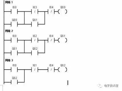
3. One-way sequential start-stop control circuit
1. The one-way sequential start control circuit is in accordance with the order pre-determined by the production process. Under the action of various input signals, each actuator in the production process automatically and orderly moves. Only after Q0.0 is started, Q0.1 can be started, and Q0.2 can only be started after Q0.1 is started.

2. The one-way sequential stop control circuit requires that the executed mechanisms be stopped in a certain order. Q0.1 can only be stopped after Q0.2 is stopped. If you want to stop Q0.0, you must stop Q0.1 first. I0.4 is the emergency stop button.
4. Delayed start and stop control circuit
1. Delayed start control To design a delayed start program, the self-locking state of the intermediate relay (internal memory M) should be used to enable the timer to count continuously. When the timing time is up, its normally open contact will act, causing Q0.0 to act.
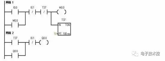
2. Delay stop control When the timing time is up, the delay stops. I0.0 is the start button and I0.1 is the stop button.

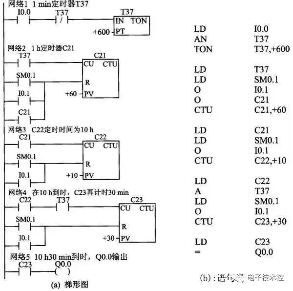
3. Delayed start-stop control circuit This circuit requires that after the input signal is received, the output signal will be turned on after a period of time; and after the input signal is OFF, the output signal will be turned off after a period of time. T37 delays 3 s as the start condition of Q0.0, and T38 delays 5 s as the shutdown condition of Q0.0.
Empirical design method and precautions
In the process of application design, the parameters that can reflect the changes in the production process should be correctly selected as control parameters for control; the mutual constraints and cooperation between the various actuators and programming components, that is, the interlocking relationship, should be correctly handled. There are many methods for designing application programs, and the commonly used design methods include empirical design method, sequential function diagram method, etc.
1. Experience Design Method
The empirical design method requires the designer to have rich practical experience and master more basic links of typical application programs. According to the requirements of the controlled object for the control system, the basic links are selected based on experience and organically combined. The design process is gradually improved, and it is generally not easy to obtain the best solution. After the preliminary design of the program, it is necessary to repeatedly debug, modify and improve until it meets the control requirements of the controlled object.
The design of the empirical design method is not standardized, there is no universal rule to follow, and it has a certain degree of tentativeness and arbitrariness.
Rules to follow when writing ladder diagram programs:
(1) The state of the "input relay" is driven by the switch signal of the external input device and the program cannot change it at will.
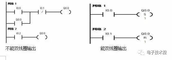
(2) A "relay coil" with the same number in a ladder diagram can only appear once and usually not appear, but its contacts can be reused indefinitely.
(3) When several series branches are connected in parallel, the branch with more contacts should be placed on the top; when several parallel circuits are connected in series, the branch with more parallel branches should be placed on the left. Ladder diagrams compiled according to this rule can reduce the number of steps in the user program and shorten the program scan time.
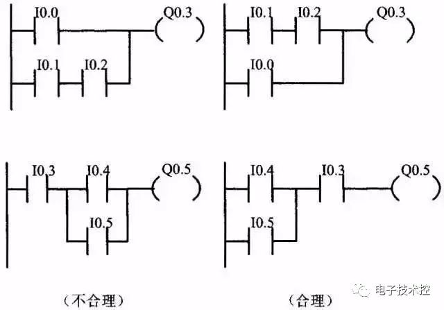
(4) The program is written in order from left to right and from top to bottom. A rung starts at the left bus and ends at the right bus, and the coil is directly connected to the right bus.
①The bridge circuit must be modified before the ladder diagram can be drawn.
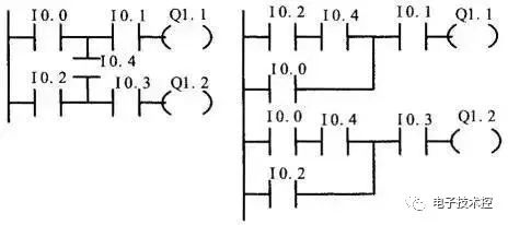
②Non-bridge complex circuits must be modified before drawing ladder diagrams

2. Notes
(1) Prepare the I/O allocation table first, then design the ladder diagram. First, assign numbers to the input and output signals and internal coils, then determine the actual wiring diagram of each PLC input/output terminal.
(2) Arrange the ladder diagram reasonably so that the input/output response lag does not affect the actual response speed. Usually, the output coils can be arranged in the order of action according to the process flow chart, while taking into account the arrangement order of internal coils, time relays and other coils, so that the input/output delayed response does not affect the actual output response speed requirements.
(3) High-speed counting instructions and high-speed pulse output instructions should be placed at the front of the entire user program as much as possible. Since the information exchange between the high-speed counter and high-speed pulse train generator and the CPU is performed during I/O scanning, the information exchange between the high-speed counter and high-speed pulse train generator and the CPU may be affected when other commands are executed, and pulses may even be lost.
(4) In the PLC input terminal wiring diagram, for the same sending element, usually only one contact (such as a normally open contact or a normally closed contact) needs to be selected to connect to the input terminal. That is, for a sending element, it can only occupy one input address number.
(5) Reasonably connect the contacts of the input signal (normally open or normally closed contacts) to improve the reliability and safety of the equipment. In the actual I/O wiring diagram of the PLC, whether a certain input signal (such as a button) is connected to the normally open contact or the normally closed contact of the electrical appliance should be considered from the perspective of the reliability and safety of the equipment. When the input terminal wiring fails and the line is disconnected, the equipment state should develop towards a safe state. Therefore, the stop button should be connected to the PLC input terminal with a normally closed contact, and the start button should be connected to the PLC input terminal with a normally open contact (for ease of understanding, the figures in the previous chapters of this book are all processed as normally open contacts).
(6) For safety reasons, important safety parts are not connected to the input terminal of the PLC, but are processed by hardware. For example, the emergency stop button, interlock contacts, emergency limit switch, thermal relay control contacts, etc. are connected to the output terminals of the PLC to directly control the output load (KM1, KM2) to ensure that the equipment is not damaged and major safety accidents are not caused when the PLC fails.
(7) The level holding time of the effective input signal should be guaranteed. To ensure that the input signal is effective, the level holding time of the input signal must be greater than one scan cycle of the PLC. Unless the pulse capture function is set for the switch input signal, the PLC is allowed to capture pulses with a very short duration.
(8) The execution conditions of PLC instructions are different, namely, signal level validity and jump validity. Please pay attention to this when programming.
(9) When converting from electrical control diagram to ladder diagram, please note: When renovating old equipment, you can refer to the original relay control circuit diagram to convert it into a ladder diagram. Most of the electrical contacts in the relay control circuit diagram are of the break-before-make type, while the state conversion of the normally open contact and the normally closed contact of the "soft relay" in the PLC ladder diagram occurs simultaneously. When designing a ladder diagram, you can use a delay circuit (such as using the internal time relay delay or the input/output delay response generated by the PLC cyclic scanning working mode) to simulate the function of the break-before-make type electrical appliance.
Sequential Function Chart and Design Method
Functional diagram and its components
Function Chart Diagram is a general language that uses a combination of graphic symbols and textual description to comprehensively describe the control system, including the control process, functions and characteristics of electrical, hydraulic, pneumatic and mechanical control systems or certain parts of the system. In the function chart, a process cycle is decomposed into several clear and continuous stages, called "steps", and the steps are separated by "conversions". When the conversion conditions between two steps are met and the conversion is realized, the activity of the previous step ends and the activity of the next step begins. The more steps a process cycle is divided into, the more accurate the description of the process is.
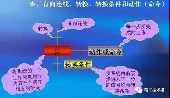
The composition of the function table diagram:
1. Step
In a working cycle of the control system, each sequentially connected working stage is called a step or a working step, which is represented by a rectangular box and text (or numbers). There are two states of a step: "active step", "inactive step", and "initial step": a series of active steps determines the state of the control process. Corresponding to the step at the beginning of the control process, each function table diagram has at least one initial step, which is represented by a double-line rectangular box.
2. Action
In the function table diagram, commands or actions are represented by rectangular text and letter symbols, which are connected to the symbols of the corresponding steps. When a step is activated, one or several actions or commands can be caused, that is, the actions of the corresponding active step are executed. If a step is an inactive step, the corresponding action returns to the state before the step is active. All actions corresponding to the active step are executed, and the action of the active step can be the start, continuation or end of the action. If there are several actions connected to the same step, these action symbols can be arranged horizontally or vertically.
Previous article:How to make PLC output a series of pulses with a specific frequency?
Next article:PLC Solutions for Industrial IoT Applications
- Popular Resources
- Popular amplifiers
- Huawei's Strategic Department Director Gai Gang: The cumulative installed base of open source Euler operating system exceeds 10 million sets
- Analysis of the application of several common contact parts in high-voltage connectors of new energy vehicles
- Wiring harness durability test and contact voltage drop test method
- Sn-doped CuO nanostructure-based ethanol gas sensor for real-time drunk driving detection in vehicles
- Design considerations for automotive battery wiring harness
- Do you know all the various motors commonly used in automotive electronics?
- What are the functions of the Internet of Vehicles? What are the uses and benefits of the Internet of Vehicles?
- Power Inverter - A critical safety system for electric vehicles
- Analysis of the information security mechanism of AUTOSAR, the automotive embedded software framework
 Professor at Beihang University, dedicated to promoting microcontrollers and embedded systems for over 20 years.
- Innolux's intelligent steer-by-wire solution makes cars smarter and safer
- 8051 MCU - Parity Check
- How to efficiently balance the sensitivity of tactile sensing interfaces
- What should I do if the servo motor shakes? What causes the servo motor to shake quickly?
- 【Brushless Motor】Analysis of three-phase BLDC motor and sharing of two popular development boards
- Midea Industrial Technology's subsidiaries Clou Electronics and Hekang New Energy jointly appeared at the Munich Battery Energy Storage Exhibition and Solar Energy Exhibition
- Guoxin Sichen | Application of ferroelectric memory PB85RS2MC in power battery management, with a capacity of 2M
- Analysis of common faults of frequency converter
- In a head-on competition with Qualcomm, what kind of cockpit products has Intel come up with?
- Dalian Rongke's all-vanadium liquid flow battery energy storage equipment industrialization project has entered the sprint stage before production
- Allegro MicroSystems Introduces Advanced Magnetic and Inductive Position Sensing Solutions at Electronica 2024
- Car key in the left hand, liveness detection radar in the right hand, UWB is imperative for cars!
- After a decade of rapid development, domestic CIS has entered the market
- Aegis Dagger Battery + Thor EM-i Super Hybrid, Geely New Energy has thrown out two "king bombs"
- A brief discussion on functional safety - fault, error, and failure
- In the smart car 2.0 cycle, these core industry chains are facing major opportunities!
- The United States and Japan are developing new batteries. CATL faces challenges? How should China's new energy battery industry respond?
- Murata launches high-precision 6-axis inertial sensor for automobiles
- Ford patents pre-charge alarm to help save costs and respond to emergencies
- New real-time microcontroller system from Texas Instruments enables smarter processing in automotive and industrial applications
- How to use SEGGER J-Trace Pro streaming mode to implement instruction tracing?
- NeoPixel Array Simulator
- 【Power amplifier application】 Lamb wave signal analysis based on dry-coupled ultrasonic testing
- Answer the questions and get a gift | Rochester Electronics will help you solve the problems of the entire semiconductor cycle
- C language (vd6.0) sleep function usage and delay usage
- Battery applications in medical monitoring and the changing environment
- Extract LEF
- Case study of the method to solve the distortion of high-frequency pulse signal measured by oscilloscope
- DA output voltage accuracy cannot be achieved
- "Playing with the board" + Yu Zhennan's STM32 development board experiment 5


 \"PLC Comprehensive Development Tool-CoDeSys Basic Programming and Application Guide\"


 京公网安备 11010802033920号