1 Composition and function of the servo system
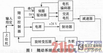
The AC follow-up system consists of an AC motor, an AC servo driver, a follow-up controller, an encoder (resolver), a reducer, etc., as shown in Figure 1.

The follow-up controller is expanded with the DSP chip as the core. It can receive the given position information transmitted by the host computer and the actual position information collected by the encoder, and output the analog voltage to the driver through the feedforward PID control algorithm to realize the control of the load motion state. The controller can collect the locking signal and limit signal of the follow-up turret and control the working state of the follow-up system.
The driver is specially designed for AC motors. It has an embedded AC motor control algorithm and forms a speed loop and a current loop with the AC motor encoder. Its internal parameters can be set using its RS-232 serial port, such as the maximum acceleration setting to ensure the response characteristics of the system. It can also receive the driver enable signal. When the enable signal is high, the motor is controlled to lock. When the enable signal is low, the motor is controlled to release the lock from the reducer.
The AC motor is the actuator of the servo system. The driver outputs three-phase AC voltage to control the speed of the motor, and finally realizes the position control of the load through the reducer.
The brake is a motor holding device used to protect the safety of the system in certain working conditions or fault conditions. When the control voltage is zero, the motor is in the holding state, and when the control voltage is +24 V, the motor is in the release state.
The power supply provides corresponding power to each component in the servo system, and at the same time controls the working state of the motor brake under the control of the servo controller.
This article mainly introduces the design of serial interface in follow-up controller and the realization of electrical limit and brake.
2 Features of DSP56F807 Processor
●The computer has independent data storage space and program storage space, and supports parallel processing; at a clock frequency of 80 MHz, it can achieve an instruction execution speed of 40 MIPS; a single instruction cycle can complete 16-bit × 16-bit parallel multiplication-addition operations.
●Special multi-function DSP instructions, that is, one instruction can complete several different operations; many related peripheral modules are integrated for motor control DSP. The integration of motor control system is increased, and the cost of the system is effectively reduced, while the reliability of the system is greatly improved.
● Support C language programming, mixed programming of C language and assembly language is more flexible and convenient. JTAG/OnCE program debugging interface allows debugging at any time during the system design process, and can debug the software in real time.
●The power supply is 3.3 V, but the input port is allowed to use 5 V TTL level.
3 Follow-up controller
The design of this part adopts the mother-daughter board architecture. The daughter board has independent reset circuit, clock circuit, and JTAG interface. The mother board only needs to design the serial port circuit, locking and limit control circuit, etc.
3.1 Design of serial port circuit
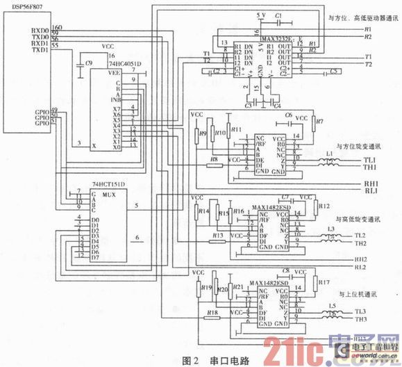
The serial port circuit is shown in Figure 2.

The follow-up controller needs to communicate with the height and position servo drive, height and position rotary transformer and host computer, but DSP56F807 has only two serial ports 0 and 1, which are far from meeting the requirements. Therefore, the two serial ports need to be expanded to 5.
GPIO RXD0 and GPIO TXD0 of serial port 0 are directly converted into RS-422 interfaces through MAX1482ESD to communicate with the host computer. GPIO RXD1 and GPIO TXD1 of serial port 1 are converted into two RS-232 interfaces through MAX3232 to communicate with the high, low and azimuth drivers respectively, and converted into two RS-422 interfaces through two MAX1482ESDs to communicate with the high, low and azimuth rotary transformers respectively.
The 8-to-1 data selector 74HCT151D is used for receiving, and the 8-channel multiplexer 74HC4051D is used for sending. The GPIO pins 49, 50, and 51 of the DSP are used as the input A, B, and C of 74HCT151D and 74HCA051D, and are decoded into 8-way receiving or sending signals from different channels.
The MAX1482ESD low-power transceiver is used to communicate with the RS-422 interface. The receiving output enable terminal RE is low, the input A is greater than B, and the receiving output terminal RO is high; conversely, the input A is less than B, and the receiving output terminal RO is low. The receiving output enable terminal RE is high, and the receiving output terminal RO is in a high-impedance state. The transmitting input enable terminal DE is high, the transmitting input terminal DI is low, the output differential signal Y is low, and the Z terminal is high; conversely, the transmitting input terminal DI is high, the output differential signal Y is high, and the Z terminal is low. When the transmitting input enable terminal DE is low, the transmitting input terminal DI is invalid, and the output terminals Y and Z are in a high-impedance state.
3.2 Electrical limit and brake
3.2.1 Types and principles of limit
Limits in the servo system can be divided into three types: software limit, electrical limit and mechanical limit.
●Software limit is to control the movement position of the system not to exceed the set position through software analysis and calculation. It is the lowest level of limit.
●Electrical limit means that when the system fails and the software limit does not play a limiting role, the system exceeds the software-limited position and continues to move. When it reaches the electrical limit position, the limit microswitch is disconnected, and the brake is put into a clamping state through circuit control, controlling the motor to stop rotating, thereby realizing the limit function.
● Mechanical limit is to limit the position of the system through the design of mechanical structure. This is the most basic and original limit method, and it is the last checkpoint of system limit. When the software limit and electrical limit are not effective, the system must be stopped at a certain position through mechanical limit (hard collision) to ensure the safety of the system.
3.2.2 Implementation of electrical limit and brake
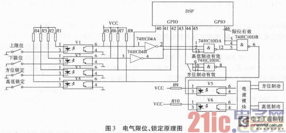
Figure 3 shows the electrical limit and locking circuit schematic:

During the initialization process, the DSP I/O port is used to detect whether the lock switch is in the closed state. If the lock switch is closed (i.e., the lock is in the locked state), the DSP sends the azimuth brake command 1, the high and low brake control command 0, and the limit control command 1. The output of the NAND gate is 0, and the photoelectric coupling tube is controlled to be in the on state. The output of the photoelectric coupling tube is used as the control end of the controllable +24 V power supply module, so that the power supply does not output +24 V voltage, and the motor brake is controlled to be in the braking state. The software will detect the lock switch status and upload it to remind the operator to release the locking device.
If the lock switch is in the open state, the DSP sends the azimuth brake command 0 and the high and low brake command 1 to detect whether the upper and lower limit switches (referring to the limit in the high and low directions, the switch is open for limit and closed for non-limit) are in the closed state. Assuming that the limit switch is in the closed state, after the DSP detects it, it sends the limit control command 0, the NAND gate output is 1, the photoelectric coupling tube is not conducting, and the power module outputs +24 V, so that the high and low motor brakes are in the non-braking state, and the motor rotation is controlled by the DSP program, and the system is in normal working condition.
During normal operation, DSP sends a limit control command of 1, an azimuth brake command of 0, and a high and low brake command of 1, so that the conduction of the photoelectric coupling tube V5 is controlled by the limit switch. When the upper and lower limit switches are in the closed state, the photoelectric coupling tube is non-conductive, and the power module outputs +24 V, so that the motor brake is in a non-braking state; as long as one of the upper and lower limit switches is in the open state, the photoelectric coupling tube is turned on, the power module output is 0 V, and the motor brake is in a braking state, thereby protecting the safety of the entire system.
4 Conclusion
The communication function of the serial port circuit is normal, the locking and limit control circuits are stable and effective, and the whole circuit has been successfully applied to a certain type of weapon system. Practice has proved that the DSP56F807, as a dedicated chip for motor control, has the following advantages: high computing speed can meet the high-performance control algorithm of the motor; large on-chip storage space (basically no external memory expansion is required) reduces user costs and improves program security; highly integrated on-chip peripherals increase the integration of the motor control system and greatly improve the reliability of the system; good software development environment, providing a large number of dedicated function libraries, greatly shortening the product development cycle.
Previous article:Design and implementation of DSP Ethernet interface based on DM9000A
Next article:Application of DSP56F807 in AC Servo System
- Huawei's Strategic Department Director Gai Gang: The cumulative installed base of open source Euler operating system exceeds 10 million sets
- Analysis of the application of several common contact parts in high-voltage connectors of new energy vehicles
- Wiring harness durability test and contact voltage drop test method
- Sn-doped CuO nanostructure-based ethanol gas sensor for real-time drunk driving detection in vehicles
- Design considerations for automotive battery wiring harness
- Do you know all the various motors commonly used in automotive electronics?
- What are the functions of the Internet of Vehicles? What are the uses and benefits of the Internet of Vehicles?
- Power Inverter - A critical safety system for electric vehicles
- Analysis of the information security mechanism of AUTOSAR, the automotive embedded software framework
 Professor at Beihang University, dedicated to promoting microcontrollers and embedded systems for over 20 years.
- Innolux's intelligent steer-by-wire solution makes cars smarter and safer
- 8051 MCU - Parity Check
- How to efficiently balance the sensitivity of tactile sensing interfaces
- What should I do if the servo motor shakes? What causes the servo motor to shake quickly?
- 【Brushless Motor】Analysis of three-phase BLDC motor and sharing of two popular development boards
- Midea Industrial Technology's subsidiaries Clou Electronics and Hekang New Energy jointly appeared at the Munich Battery Energy Storage Exhibition and Solar Energy Exhibition
- Guoxin Sichen | Application of ferroelectric memory PB85RS2MC in power battery management, with a capacity of 2M
- Analysis of common faults of frequency converter
- In a head-on competition with Qualcomm, what kind of cockpit products has Intel come up with?
- Dalian Rongke's all-vanadium liquid flow battery energy storage equipment industrialization project has entered the sprint stage before production
- Allegro MicroSystems Introduces Advanced Magnetic and Inductive Position Sensing Solutions at Electronica 2024
- Car key in the left hand, liveness detection radar in the right hand, UWB is imperative for cars!
- After a decade of rapid development, domestic CIS has entered the market
- Aegis Dagger Battery + Thor EM-i Super Hybrid, Geely New Energy has thrown out two "king bombs"
- A brief discussion on functional safety - fault, error, and failure
- In the smart car 2.0 cycle, these core industry chains are facing major opportunities!
- The United States and Japan are developing new batteries. CATL faces challenges? How should China's new energy battery industry respond?
- Murata launches high-precision 6-axis inertial sensor for automobiles
- Ford patents pre-charge alarm to help save costs and respond to emergencies
- New real-time microcontroller system from Texas Instruments enables smarter processing in automotive and industrial applications
- Share the use of Allegro Color command with everyone
- Comparison of technical indicators between N76E003AT20 and STM8S003F3P6
- [HPM-DIY] openmv for hpm6750 Progress 2 (face recognition 29fps+)
- I have three Mitsubishi PLCs, model FX3U, can they realize 485 wireless communication?
- 51 drives ST7920 to display custom size characters at any position. I don't know why it flashes when refreshing. Please guide me
- How to flash the customized version of the Saida card machine
- Multitasking in Circuit Python
- CCS variable observer problem
- Creative Collection | The CH246 & CH241 wireless charging kit is ready, what are you going to DIY with it?
- Electromagnetic interference is no small matter, EMI prize survey is launched!

 Brakes, brake control and driver assistance systems (BOSCH)


 京公网安备 11010802033920号