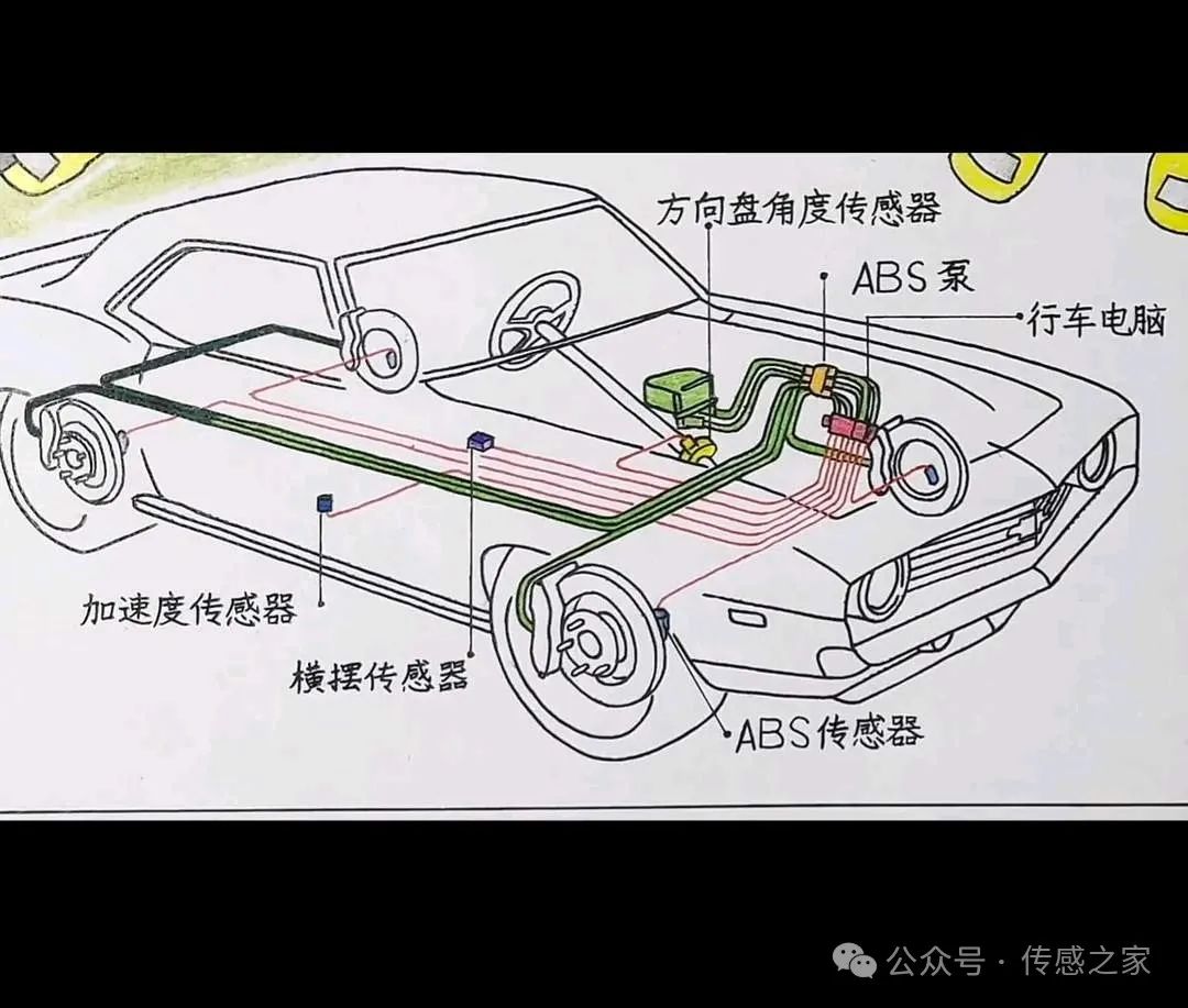
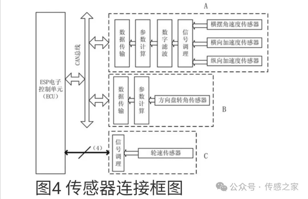
1. Wheel speed sensor: The wheel speed sensor usually uses magnetic induction or Hall effect principle to detect the rotation speed of the wheel. When the wheel rotates, the sensor generates an electrical signal proportional to the wheel speed, which is transmitted to the ESP control unit.
2. Steering angle sensor: The steering angle sensor usually measures the steering angle and speed of the steering wheel through a potentiometer or optical sensor. It can detect the driver's steering intention and provide information about the vehicle's steering direction and angular velocity.
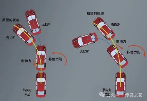
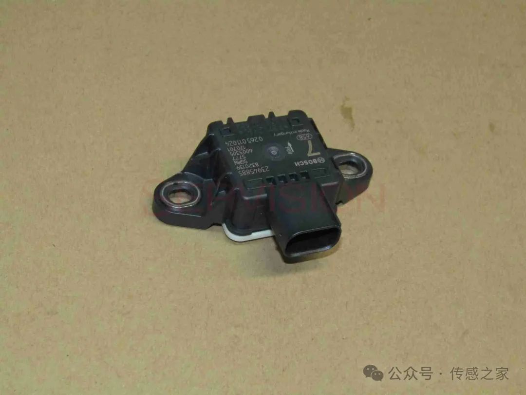
3. Yaw rate sensor: The yaw rate sensor is used to measure the rotation speed of the vehicle around its vertical axis. This can be achieved through principles such as gyroscopes or accelerometers. The sensor detects the yaw motion of the vehicle and transmits the data to the ESP system.
Previous article:Arteli AT32A423 new automotive-grade MCU released
Next article:The world's first 4nm automotive cockpit chip: MediaTek MT8676, which surpasses Qualcomm SA8295, is about to be installed in the car
- Popular Resources
- Popular amplifiers
Latest Automotive Electronics Articles
- Car key in the left hand, liveness detection radar in the right hand, UWB is imperative for cars!
- After a decade of rapid development, domestic CIS has entered the market
- Aegis Dagger Battery + Thor EM-i Super Hybrid, Geely New Energy has thrown out two "king bombs"
- A brief discussion on functional safety - fault, error, and failure
- In the smart car 2.0 cycle, these core industry chains are facing major opportunities!
- The United States and Japan are developing new batteries. CATL faces challenges? How should China's new energy battery industry respond?
- Murata launches high-precision 6-axis inertial sensor for automobiles
- Ford patents pre-charge alarm to help save costs and respond to emergencies
- New real-time microcontroller system from Texas Instruments enables smarter processing in automotive and industrial applications
MoreSelected Circuit Diagrams
MorePopular Articles
- Innolux's intelligent steer-by-wire solution makes cars smarter and safer
- 8051 MCU - Parity Check
- How to efficiently balance the sensitivity of tactile sensing interfaces
- What should I do if the servo motor shakes? What causes the servo motor to shake quickly?
- 【Brushless Motor】Analysis of three-phase BLDC motor and sharing of two popular development boards
- Midea Industrial Technology's subsidiaries Clou Electronics and Hekang New Energy jointly appeared at the Munich Battery Energy Storage Exhibition and Solar Energy Exhibition
- Guoxin Sichen | Application of ferroelectric memory PB85RS2MC in power battery management, with a capacity of 2M
- Analysis of common faults of frequency converter
- In a head-on competition with Qualcomm, what kind of cockpit products has Intel come up with?
- Dalian Rongke's all-vanadium liquid flow battery energy storage equipment industrialization project has entered the sprint stage before production
MoreDaily News
- Allegro MicroSystems Introduces Advanced Magnetic and Inductive Position Sensing Solutions at Electronica 2024
- Car key in the left hand, liveness detection radar in the right hand, UWB is imperative for cars!
- After a decade of rapid development, domestic CIS has entered the market
- Aegis Dagger Battery + Thor EM-i Super Hybrid, Geely New Energy has thrown out two "king bombs"
- A brief discussion on functional safety - fault, error, and failure
- In the smart car 2.0 cycle, these core industry chains are facing major opportunities!
- The United States and Japan are developing new batteries. CATL faces challenges? How should China's new energy battery industry respond?
- Murata launches high-precision 6-axis inertial sensor for automobiles
- Ford patents pre-charge alarm to help save costs and respond to emergencies
- New real-time microcontroller system from Texas Instruments enables smarter processing in automotive and industrial applications
Guess you like
- How do you spend the May Day holiday?
- [Chuanglong Technology Allwinner A40i Development Board] Qt performance test
- Antai Instruments Repair Sharing - Tektronix Oscilloscope Repair DPO5054B
- You can't change actors in a serialized TV series, otherwise it will become a different movie.
- The transformer in the power supply has no output after loading
- Compile imx6-ek200 with buildroot
- Using MSP430 to implement PWM signal
- Get the MPM54304 evaluation board for the first quad-output module with digital power management
- Dead time problem of IGBT drive waveform
- The difference between single-phase carrier and type 2 collector

 LMV1012UPX-25


 京公网安备 11010802033920号