1 Introduction
Virtual instrument (VI-ViItuaIInstrument) refers to the combination of general-purpose computers and functional hardware through applications. Users can operate the computer through a friendly graphical interface, just like operating a single instrument defined and designed by themselves, thereby completing Collection, processing, analysis, judgment, display, data storage, etc. of the measured data. In this kind of instrument system, various complex test functions, data analysis and result display are all completed by computer software. In many aspects, it has incomparable advantages over traditional instruments, such as flexible and convenient use, rich test functions, low price, and one-stop service. These make virtual instruments become one of the main directions for the development of electronic measuring instruments in the future.
The buses used in today's virtual instrument system development include the traditional Rs232 serial bus, GPIB general interface bus, VXI bus, PCI bus and IEEE 1394 bus, which is Firewire (also called Firewire).
This article introduces a fast virtual oscilloscope test system based on the PCI bus interface CompuS, cope82G high-speed data acquisition card and Visual C++ programming tool. This system integrates waveform acquisition, data analysis, output, and display. In order to ensure the real-time performance of data acquisition and waveform display, multi-threading technology is also used in the design.
2 System composition and hardware structure of acquisition card
2.1 System composition
The virtual oscilloscope system is mainly composed of data acquisition card, computer and special software. Among them, the data acquisition card completes the conditioning, acquisition and caching of the input measurement signals, and transmits them through the computer PCI bus. Send it into the memory; the computer processes and calculates the data under the control of the application program, and finally completes various power tests and displays them on the screen in the form of graphics or data. All this is done in human-computer interaction mode.
2.2 Hardware structure of data acquisition card
This virtual oscilloscope uses the CompuScope82G high-speed data acquisition card of Gage Company as the PCI interface. The hardware structure of the capture card is shown in Figure 1.

The data acquisition card is mainly composed of pre-filter, programmable attenuator, programmable analog amplifier circuit, A/D converter, D/A converter, counting, timing circuit, oscillation circuit, timing control circuit and PCI interface circuit , whose functional circuits are uniformly controlled by digital control logic circuits. The card is a standard PCI bus plug-in card with 2 analog input channels. The two high-speed 8-bit ADCs integrated on the card have a working frequency up to 1GHz. In single-channel working mode, the two ADCs work at the same time. The rising and falling edges are converted, so the maximum sampling frequency can reach 2GHz. The card is equipped with 16M high-speed memory, which solves the problem of matching high sampling rate and relatively low PCI bus data transmission rate. The hardware of the capture card must be configured before use. These control programs use the corresponding underlying DAQ driver. Through the DLL that comes with the acquisition card, the hardware can be flexibly controlled in the program, such as input impedance, input voltage range, amplifier gain, sampling frequency, number of sampling points per time, etc.
3 System software design
3.1 Software development environment of virtual oscilloscope
The core technology of virtual instrument is software technology. At present, there are two main categories of software development platforms used for virtual instrument development: one is a general visual software programming environment, mainly including Microsoft's Visual C++ and Visual Basic, Inprise's Delphi and C++Builder, etc.; the other is a general visual software programming environment. The first category is the programming environment dedicated to virtual instrument development software launched by some companies, mainly including NI's graphical programming environment LabView and text programming environment IabWindows/CVI, and Agilent's graphical programming environment Agilent VEE. Considering the flexibility, efficiency and portability of the software, visual C++ is used as the development environment of the virtual oscilloscope in this design.

3.2 Software function modules
The virtual oscilloscope has five major functional modules: signal acquisition, user interface, spectrum analysis, digital filtering, and waveform display.
3.2.1 Signal acquisition module
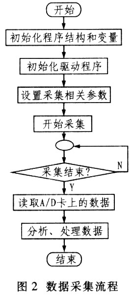
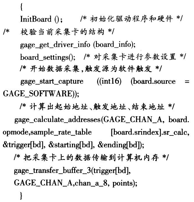
The signal acquisition module mainly completes the collection of data, and selects different sampling frequencies according to the different signals collected. The application program in this module communicates with the hardware through the driver of the capture card. If this module is implemented in the main thread of the program, the main interface will freeze when the application program communicates with the driver. In order to solve this problem, this article directly creates a sub-thread to complete the communication task with the driver alone, allowing the main interface to be dedicated to responding to information from the window interface. Data is collected in the child thread by calling the gage_start_capture() function. Figure 2 shows the data collection process. The main code for data collection is as follows:
? 
3.2.2 The user interface module
interface is mainly divided into 3 views: the main view base class is ScrollView, which is used to display waveforms; the 2 view base classes are For-mView, and 1 is used to dynamically display the characteristics of the collected data. parameters, and the other one is used to operate the oscilloscope. The main interface design of the entire software is shown in Figure 3.

3.2.3 Spectrum analysis module
This software uses Fast Fourier Transform (FFT) to perform spectrum analysis. Spectrum analysis uses a time-based extraction FFT algorithm, and then the amplitude spectrum analysis results are displayed in the form of a coordinate curve on the user interface. You can choose the number of points when performing FFT. There are 3 choices: 1024, 2048, and 4096. If the number of points is not enough, the program will automatically fill in zeros.
3.2.4 Digital filter module
This software can perform low-pass and high-pass filtering on the collected signals. Firstly, a Butter-worth analog filter is designed based on the given passband cutoff frequency, stopband cutoff frequency, passband attenuation and stopband attenuation, and then a digital filter is designed using the bilinear transformation method.
3.2.5 Waveform display module
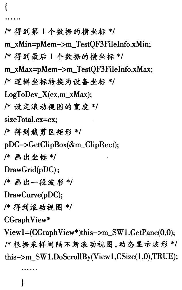
The working principle of the virtual oscilloscope is to sample the signal waveform at high speed. The sampled values are digitized and stored. When the waveform is reconstructed, the numbers are fetched from the buffer, and then a clear and uniform trajectory image is used. on the screen. Since the collected analog waveform is digitized and becomes a series of discrete data, how to reconstruct the signal waveform is one of the key issues in the design of virtual oscilloscopes. The current waveform display mainly includes segmented display and rolling display. Here, scrolling display is used, and a new scrolling display algorithm is proposed, which breaks through the limitation that scrolling display can only observe slowly changing signals. The core idea of the algorithm is as follows:
(1) Obtain the abscissa m_xMin and rn_xMax of the first and last data points of the collected data block, m_xMax-m_xMin is the logical width of the waveform.
(2) The values of m_xMax-m_xMin are logical coordinates, convert them into device coordinates cx, and use cx to set the width of the entire
scroll view.
(3) In order to improve the efficiency of drawing, you only need to draw the graphics of the visible part of the scroll view, that is, the graphics of the clipping area, so you need to get the clipping area.
(4) Draw a waveform within the coordinates and clipping area.
(5) Use the CSplitterWnd::DoSerollBy() function to determine the speed of the scroll view based on the size of the sampling interval. In this way, the corresponding clipping area will also change after the view is scrolled, prompting new waveforms to be drawn dynamically.
The main code is as follows:
? 
4 Experiment and Discussion
In the experiment, the system was used to collect sine signals and sawtooth wave signals, and spectrum analysis was performed on the signals of the two channels. During the experiment, the oscilloscope parameters were set as follows: the sampling mode is dual channel, where channel 1 samples the sine signal and channel 2 samples the sawtooth signal; the sampling rate is 120Ms/s; the sampling depth is 16 000 points; the trigger source is software trigger ;The trigger time limit is 20ms; the input signal voltage range is ~5V. The experimental results are shown in Figure 4. The intended effect was achieved.

This article designs a fast virtual oscilloscope test system based on Gage's CompuScope 82G high-speed data acquisition card and uses Visual C++ programming tools to achieve high-speed data collection and dynamic waveform display. At the same time, a new waveform rolling algorithm is proposed, which greatly improves the dynamic display effect of rolling waveforms. On this basis, spectrum analysis and digital filtering functions that cannot be achieved with traditional oscilloscopes are realized. Using Visual C++ as the instrument programming language makes the programs written highly versatile and portable.
Previous article:Intelligent instrument design based on HT47 series RISC microcontroller
Next article:Design and implementation of transformer test system based on MCU CPLD
Recommended ReadingLatest update time:2024-11-16 17:43

- Popular Resources
- Popular amplifiers
- Keysight Technologies Helps Samsung Electronics Successfully Validate FiRa® 2.0 Safe Distance Measurement Test Case
- From probes to power supplies, Tektronix is leading the way in comprehensive innovation in power electronics testing
- Seizing the Opportunities in the Chinese Application Market: NI's Challenges and Answers
- Tektronix Launches Breakthrough Power Measurement Tools to Accelerate Innovation as Global Electrification Accelerates
- Not all oscilloscopes are created equal: Why ADCs and low noise floor matter
- Enable TekHSI high-speed interface function to accelerate the remote transmission of waveform data
- How to measure the quality of soft start thyristor
- How to use a multimeter to judge whether a soft starter is good or bad
- What are the advantages and disadvantages of non-contact temperature sensors?
- Innolux's intelligent steer-by-wire solution makes cars smarter and safer
- 8051 MCU - Parity Check
- How to efficiently balance the sensitivity of tactile sensing interfaces
- What should I do if the servo motor shakes? What causes the servo motor to shake quickly?
- 【Brushless Motor】Analysis of three-phase BLDC motor and sharing of two popular development boards
- Midea Industrial Technology's subsidiaries Clou Electronics and Hekang New Energy jointly appeared at the Munich Battery Energy Storage Exhibition and Solar Energy Exhibition
- Guoxin Sichen | Application of ferroelectric memory PB85RS2MC in power battery management, with a capacity of 2M
- Analysis of common faults of frequency converter
- In a head-on competition with Qualcomm, what kind of cockpit products has Intel come up with?
- Dalian Rongke's all-vanadium liquid flow battery energy storage equipment industrialization project has entered the sprint stage before production
- Allegro MicroSystems Introduces Advanced Magnetic and Inductive Position Sensing Solutions at Electronica 2024
- Car key in the left hand, liveness detection radar in the right hand, UWB is imperative for cars!
- After a decade of rapid development, domestic CIS has entered the market
- Aegis Dagger Battery + Thor EM-i Super Hybrid, Geely New Energy has thrown out two "king bombs"
- A brief discussion on functional safety - fault, error, and failure
- In the smart car 2.0 cycle, these core industry chains are facing major opportunities!
- The United States and Japan are developing new batteries. CATL faces challenges? How should China's new energy battery industry respond?
- Murata launches high-precision 6-axis inertial sensor for automobiles
- Ford patents pre-charge alarm to help save costs and respond to emergencies
- New real-time microcontroller system from Texas Instruments enables smarter processing in automotive and industrial applications
- What do you think about RF company Qorvo providing programmable power for smart home appliances?
- Design of SAW RFID system based on DSP device TMS320VC5509A chip
- Analysis of the "Signal" topic in the National College Student Electronics Contest
- I have just started learning Cadence Virtuoso and found that as long as the schematic diagram appears in the parallel inductor simulation, an error will be reported.
- The college entrance examination results are announced! How are the top scorers around you doing now?
- How to use an oscilloscope to test the transient energy of a battery
- What frequency ESR should we choose for the output filter capacitor of a flyback power supply?
- LAN Problems
- [National Technology N32 MCU Development Data] - Datasheet download link
- RTC solution selection

 Basics of Machine Learning: From Getting Started to Job Hunting (Hu Huanwu)
 CVPR 2023 Paper Summary: Transparency, Fairness, Accountability, Privacy, Ethics in Vision


 京公网安备 11010802033920号