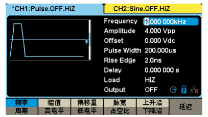
First we turn on an SDG6000X-E and an oscilloscope. Connect the generator channel 1 and the oscilloscope channel 1 through the BNC cable.
First set up SDG6000X-E, select sine wave, set: frequency 20MHz, amplitude 1Vp-p, Offset: 0, phase: 0°, turn on output: output
Click autosetup on the oscilloscope, and then add measurement (Measurement-Basic Measurement). At this time, the frequency and amplitude of the waveform can be read.

Then we try the output grid pulse waveform: also click on the screen to select pulse
Frequency setting: 20M; Amplitude: 1Vp-p; Offset: 0; Pulsewidth: 20ns
At this time, the oscilloscope will display a pulse waveform. Similarly, we add measurements. In the measurement menu-select basic measurement-clear measurement, then click measurement again-menu-select type---horizontal measurement---select frequency and positive pulse width.
At this time, the measurement results will be displayed at the bottom of the screen. The measurement results should be consistent with our settings

How to modulate the modulated signal generated by the arbitrary wave generator?
First, why do we modulate the signal.
1) The original electrical signal at the sending end in the communication system usually has a very low frequency spectrum component and is generally not suitable for direct transmission in the channel. Therefore, it is usually necessary to transform the original signal into a signal with a frequency band suitable for channel transmission.
2) Multiple baseband signals can be moved to different spectrums through modulation, thereby making full use of the channel and improving transmission performance.
3) Modulation can expand the bandwidth of wireless communication signals, thereby improving the ability to resist interference and fading.
4) Reduce the size of transmitting and receiving antennas in wireless communications.
Okay, let's use this arbitrary wave generator to generate a modulated signal.
Settings section:
Set the arbitrary wave generator channel 1, open the front panel Mod, select AM as the modulation type, select internal as the source, 80% modulation depth, sine as the modulation waveform, 500khz as the modulation frequency, set the frequency as Frequency—10Mhz; and the amplitude as Amplitude—1Vp— p; other defaults.
Then connect channel 1 to channel 1 of the oscilloscope through the BNC cable, open the arbitrary waveform channel 1 output, click the oscilloscope autosetup, and then click the RUN/stop button to stop the acquisition. At this time, the oscilloscope displays the modulation waveform normally. Then add - Measurement - Basic Measurement - you can see that the peak-to-peak voltage at this time is about 1.8V.
By calculating the amplitude ratio before and after modulation is 80%, which is consistent with the 80% modulation depth we set.
With the same principle, you can try other modulation methods, such as FM, ASK, and FSK. If you have any questions, please contact Boyuxunming engineers to assist you in modulating the arbitrary wave generator.
Previous article:A brief introduction to signal generators
Next article:Characteristics and application areas of high-frequency current probes
- Popular Resources
- Popular amplifiers
- New IsoVu™ Isolated Current Probes: Bringing a New Dimension to Current Measurements
- Modern manufacturing strategies drive continuous improvement in ICT online testing
- Methods for Correlation of Contact and Non-Contact Measurements
- Keysight Technologies Helps Samsung Electronics Successfully Validate FiRa® 2.0 Safe Distance Measurement Test Case
- From probes to power supplies, Tektronix is leading the way in comprehensive innovation in power electronics testing
- Seizing the Opportunities in the Chinese Application Market: NI's Challenges and Answers
- Tektronix Launches Breakthrough Power Measurement Tools to Accelerate Innovation as Global Electrification Accelerates
- Not all oscilloscopes are created equal: Why ADCs and low noise floor matter
- Enable TekHSI high-speed interface function to accelerate the remote transmission of waveform data
- Intel promotes AI with multi-dimensional efforts in technology, application, and ecology
- ChinaJoy Qualcomm Snapdragon Theme Pavilion takes you to experience the new changes in digital entertainment in the 5G era
- Infineon's latest generation IGBT technology platform enables precise control of speed and position
- Two test methods for LED lighting life
- Don't Let Lightning Induced Surges Scare You
- Application of brushless motor controller ML4425/4426
- Easy identification of LED power supply quality
- World's first integrated photovoltaic solar system completed in Israel
- Sliding window mean filter for avr microcontroller AD conversion
- What does call mean in the detailed explanation of ABB robot programming instructions?
- RAQ #223: How to measure and determine soft-start timing without a soft-start equation?
- RAQ #223: How to measure and determine soft-start timing without a soft-start equation?
- GigaDevice's full range of automotive-grade SPI NOR Flash GD25/55 wins ISO 26262 ASIL D functional safety certification
- GigaDevice's full range of automotive-grade SPI NOR Flash GD25/55 wins ISO 26262 ASIL D functional safety certification
- New IsoVu™ Isolated Current Probes: Bringing a New Dimension to Current Measurements
- New IsoVu™ Isolated Current Probes: Bringing a New Dimension to Current Measurements
- Infineon Technologies Launches ModusToolbox™ Motor Kit to Simplify Motor Control Development
- Infineon Technologies Launches ModusToolbox™ Motor Kit to Simplify Motor Control Development
- STMicroelectronics IO-Link Actuator Board Brings Turnkey Reference Design to Industrial Monitoring and Equipment Manufacturers
- Melexis uses coreless technology to reduce the size of current sensing devices
- Ethernet plays an important role in the manufacturing industry
- Switching Power Supply Interest Group Task 02
- Say goodbye to 2018 and welcome 2019. See how the three pillars of China Mobile IoT dominate the field
- Using MakeCode Driver on BrainPad Development Board
- Car Radio Audio Signal Processor (Front End)
- Please tell me the function of STM32 WWDG window value
- How does positioning technology change the world?
- 2. Sensors used in previous "Control" competitions
- Applications of MC1413
- The left side is connected to the microcontroller, and the right side is the button. Why is the IO port always at a high level?

 HA9P5033-5


 京公网安备 11010802033920号