As a product of Tektronix, Keithley Sourcemeter is as famous as Tektronix oscilloscopes. However, some users found that errors were introduced by resistors when using Keithley's source meter multimeter, so how to eliminate them? Today Antai Testing will introduce to you the four-wire testing method. The four-wire test method is by far the best test solution for eliminating (or minimizing) errors introduced by lead resistance.
Two-wire measurement method:
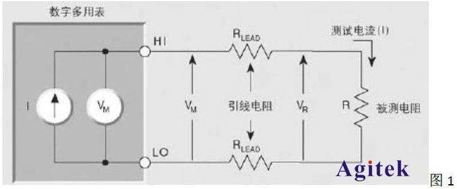
Traditional resistance measurement usually uses a two-wire measurement method, such as our most commonly used handheld multimeter. When measuring, you only need to point the red and black test leads on the left and right ends of the resistance to be measured, and the multimeter will automatically add an excitation current or voltage (the automatic excitation size is related to the selected gear, and the excitation size in the multimeter cannot be adjusted). While adding excitation voltage, test the current at both ends of the device under test; or while adding excitation current, test the voltage at both ends of the device under test. Then obtain the resistance value through Ohm's law R=U/I. As shown in Figure 1,

in:
I is the excitation current (test current)
VM is the voltage measured by the multimeter
RLEAD is the lead resistance
R is the measured resistance
HI and LO are the output and input terminals of the multimeter.
The measurement result is R=VM/I. From the working circuit diagram in Figure 1, we can know that this test result actually contains two parts: the measured resistance R and the two lead resistances 2*RLEAD. Typical lead resistance values are roughly 1 milliohm to 10 milliohms. Of course, when the resistance of the measured resistor is large, the influence of the lead resistance can be ignored; but when the measured resistance is small or the test accuracy is required, At higher values, the additional error source of lead resistance cannot be ignored.
Rel options:
Some new handheld multimeters on the market are designed with a rel option (desktop multimeters generally have it), such as Keithley's desktop multimeter. Its working principle is: before testing and measuring, short-circuit the red and black test leads to obtain the lead resistance value and Record this data, and directly subtract the recorded lead resistance value from the resistance value measured later. Use this mathematical method to reduce errors and improve measurement accuracy. The result is: R=(VM/I) -2*RLEAD. Under normal circumstances, this measurement method is simple and easy to use, and its accuracy is higher than the two-wire measurement method. However, during the actual measurement process, the lead resistance RLEAD is not a constant value, and the resistance value will also change as the temperature environment changes. In the mathematical calculation process of the Rel function, the lead resistance at the moment when the rel option is pressed is brought into the calculation. If the tester has higher requirements for test measurement accuracy, it is recommended to use the four-wire method for measurement.
Four-wire test method:
The four-wire test method is by far the best test solution for eliminating (or minimizing) errors introduced by lead resistance. The principle is: add a set of sampling leads on the basis of the two-wire method, and use the test results of the sampling leads to replace the measurement results of the test leads for calculation, thereby obtaining a more accurate resistance value. as shown in picture 2,

in:
I is the excitation current
VM is the voltage measured by the multimeter
RLEAD is the lead resistance
R is the measured resistance
Source HI and source LO are the output excitation current terminals of the multimeter.
Sampling HI and sampling LO are the sampling leads, which is the input voltage VM terminal.
During the entire test process, there was no voltage drop on the sampling lead, so the lead resistance 2*RLEAD did not affect the test. The measured voltage VM is basically the same as the actual voltage on the measured resistor R, that is, the measurement result is still R=VM/I. Although there is still a tiny current flowing through the sampling lead, it can be ignored in actual measurements. Compared with the two-wire testing method, the resistance value measured by the four-wire testing method does not contain lead resistance, so the accuracy is higher than the two-wire testing method.
Take the Keithley 2400 series as an example: http://www.agitek.com.cn/chanpin-s-80-587.html

Keithley 2400 series
Keithley 2400 series
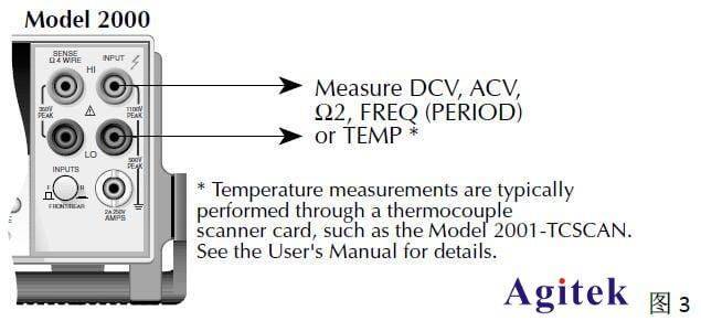
When using the two-wire test method, only the HI and LO terminals of the input need to be connected. As shown in Figure 3,

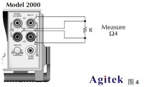
When using the four-wire test method, you need to connect the four input ports of HI, LO, Sense HI, and Sense LO (Sense HI and Sense LO are sampling lead interfaces). As shown in Figure 4

Special attention needs to be paid: the sampling lead terminals (Sense HI and Sense LO) should be as close as possible to both ends of the resistance being measured. The farther the distance, the more test lead resistance is introduced. As shown in Figure 5, there is still a long section of lead between the contact point of the sampling lead and the resistance being measured. This connection method will increase the error.

This method can be applied to Keithley 2001 series, Keithley 2002 series, Keithley 2010 series, DAQ6510, DMM6500 multimeter, Keithley 2100 series, Keithley 2110 series, Tektronix 4000 series, Keithley 2700 multimeter/data acquisition/switching system, etc.
Previous article:Introduction to the technical parameters of Keithley Source Meter 2635A
Next article:Keysight Technologies Keysight 34461A digital multimeter
- Keysight Technologies Helps Samsung Electronics Successfully Validate FiRa® 2.0 Safe Distance Measurement Test Case
- From probes to power supplies, Tektronix is leading the way in comprehensive innovation in power electronics testing
- Seizing the Opportunities in the Chinese Application Market: NI's Challenges and Answers
- Tektronix Launches Breakthrough Power Measurement Tools to Accelerate Innovation as Global Electrification Accelerates
- Not all oscilloscopes are created equal: Why ADCs and low noise floor matter
- Enable TekHSI high-speed interface function to accelerate the remote transmission of waveform data
- How to measure the quality of soft start thyristor
- How to use a multimeter to judge whether a soft starter is good or bad
- What are the advantages and disadvantages of non-contact temperature sensors?
- Innolux's intelligent steer-by-wire solution makes cars smarter and safer
- 8051 MCU - Parity Check
- How to efficiently balance the sensitivity of tactile sensing interfaces
- What should I do if the servo motor shakes? What causes the servo motor to shake quickly?
- 【Brushless Motor】Analysis of three-phase BLDC motor and sharing of two popular development boards
- Midea Industrial Technology's subsidiaries Clou Electronics and Hekang New Energy jointly appeared at the Munich Battery Energy Storage Exhibition and Solar Energy Exhibition
- Guoxin Sichen | Application of ferroelectric memory PB85RS2MC in power battery management, with a capacity of 2M
- Analysis of common faults of frequency converter
- In a head-on competition with Qualcomm, what kind of cockpit products has Intel come up with?
- Dalian Rongke's all-vanadium liquid flow battery energy storage equipment industrialization project has entered the sprint stage before production
- Allegro MicroSystems Introduces Advanced Magnetic and Inductive Position Sensing Solutions at Electronica 2024
- Car key in the left hand, liveness detection radar in the right hand, UWB is imperative for cars!
- After a decade of rapid development, domestic CIS has entered the market
- Aegis Dagger Battery + Thor EM-i Super Hybrid, Geely New Energy has thrown out two "king bombs"
- A brief discussion on functional safety - fault, error, and failure
- In the smart car 2.0 cycle, these core industry chains are facing major opportunities!
- The United States and Japan are developing new batteries. CATL faces challenges? How should China's new energy battery industry respond?
- Murata launches high-precision 6-axis inertial sensor for automobiles
- Ford patents pre-charge alarm to help save costs and respond to emergencies
- New real-time microcontroller system from Texas Instruments enables smarter processing in automotive and industrial applications
- NeoPixel Infinity Cube
- [STM32F769Discovery development board trial] Discussion and application of DMA2D screen refresh efficiency
- Compilation of TI DM8148 multi-core DSP SDK
- Thank you for being here + my proactive change
- Using Energia to develop MSP430F5529LP under Windows 10 Basic process and problems encountered
- Wi-Fi 6E has been launched. What is the difference between it and ordinary Wi-Fi?
- uboot operates gpio level
- This is the window that pops up when I open the component library in AD17. What's going on?
- RVB2601 Evaluation Board Trial 3: Ethernet Communication Test
- UNI-T UT70B Multimeter Schematic Diagram and Instruction Manual (EN)

 keithely2400 two interconnected
 2013keithley main product catalog


 京公网安备 11010802033920号