A high-precision instrument is determined by a variety of high-precision components with high accuracy and high stability of analog circuits, and the biggest destroyer of this circuit is temperature. Here we will introduce the impact of temperature on high-precision instruments.
1. Temperature can affect the physical properties of components
1. Impact on diode volt-ampere characteristics
When the ambient temperature rises, the forward characteristic curve of the diode will shift to the left, and the reverse characteristic curve will shift downward, as shown in Figure 1. Near room temperature, the forward voltage drop decreases by 2~2.5mV for every 1℃ increase in temperature; the reverse current increases by about one-fold for every 10℃ increase in temperature. It can be seen that the characteristics of the diode are very sensitive to temperature.
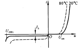
Figure 1. The volt-ampere characteristics of a diode
2. Impact on transistor input and output characteristics
Due to the thermal sensitivity of semiconductor materials, almost all parameters of transistors are related to temperature.
The influence of temperature on input characteristics: Similar to the diode volt-ampere characteristics, when the temperature rises, the positive offset will shift to the left, and vice versa, it will shift to the right, as shown in Figure 2.
The influence of temperature on output characteristics: As shown in Figure 3, the solid line and the dotted line are the characteristic curves at 20℃ and 60℃ respectively. It can be seen that when the temperature rises, the collector current increases due to the left shift of the input characteristics.
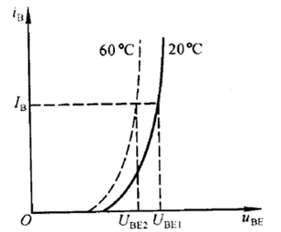
Figure 2 Effect of temperature on transistor input characteristics
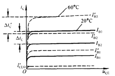
Figure 3 Effect of temperature on transistor output characteristics
2. Stabilize the static operating point and suppress temperature drift
Among the many factors that cause the instability of the static operating point, the influence of temperature on transistor parameters is the most important. The so-called stable static operating point and suppressed temperature drift usually means that when the ambient temperature changes, the static collector current and tube voltage drop of the transistor remain basically unchanged, and the change of the base electrode current must be relied upon to offset the change of the collector current. The commonly used method is to use DC negative feedback or temperature compensation to make the base current produce a change opposite to the collector current when the temperature changes.
3. Necessity of instrument preheating
Depending on the purpose and precision level of the instrument, some need to be preheated, while others do not. The preheating of the instrument is to achieve thermal stability and balance of the internal electronic components. It takes a certain amount of time for the capacitors, inductors, transistors, etc. in the circuit to reach a steady state, and preheating is necessary to reduce measurement errors. The more precise the instrument, the longer the preheating time.
4. How does ZHIYUAN Electronics Power Analyzer make the measurement results more accurate?
1. Before using the instrument, it is necessary to preheat the instrument;
2. Before the measurement begins, a zero adjustment operation is required. Zero adjustment refers to the process of creating a state where the input signal is zero in the internal circuit of the power analyzer and setting the calculation result in this state to a zero level in a numerical sense;
3. Selecting the appropriate range, update rate and synchronization source is crucial to the measurement accuracy of the power analyzer. For example, when the update period is less than the period of the measured signal, as shown in Figure 4 below, the data within the entire update period becomes the measurement interval, and the sampled data within the entire update period will be averaged, thus affecting the accuracy of the measurement result. In this case, the update period needs to be increased so that the measured signal containing more periods enters the measurement interval;
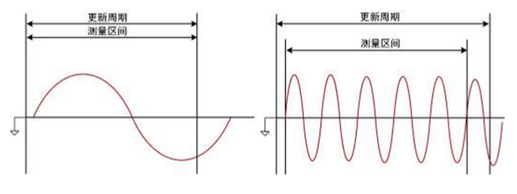
Figure 4 Comparison of update cycles
4. Reduce the influence of stray capacitance on the measurement results. Because the instrument housing and the shielding box of the internal measurement circuit are insulated, there is stray capacitance between the two. Connecting the current measurement loop to the low voltage side, as shown in Figure 5, that is, connecting the current input terminal of the instrument to the end close to the ground potential of the power supply (Source), can effectively reduce the influence of stray capacitance on the measurement accuracy.

Figure 5 Wiring diagram
5. To reduce the impact of power loss, when measuring large current, the voltage measurement circuit needs to be connected to the side close to the load. The result measured by the current measurement circuit is the sum of the current flowing through the load and the voltage measurement circuit. The measurement error is only the current flowing through the voltage measurement circuit.
When measuring small currents, the current measurement loop needs to be connected to the side close to the load. The result measured by the voltage measurement loop is the difference between the load voltage and the voltage of the current measurement loop. The measurement error is only the voltage across the current measurement loop; as shown in Figure 6.

Figure 6 Wiring diagram under different currents
The ZHIYUAN Electronics PA power analyzer uses a high-stability temperature-compensated 100M synchronous clock to ensure the phase synchronization of ADC sampling of each channel, and the voltage and current phase error is within 10ns. In the module control unit of the host part, we use a high-stability temperature-compensated 100M synchronous clock. This clock signal will be sent to the ADC of each channel to ensure the ADC sampling phase synchronization. The voltage and current errors between single channels can be guaranteed to be within 10ns, reducing the error introduced by the instrument itself during measurement of the U and I angles, and ensuring the accuracy of active power and power factor measurement! The industry has the problem that the power factor is too low or too low to be accurately measured, which has a lot to do with the error introduced by the instrument itself and the test method. Before the launch of the ZHIYUAN Electronics power analyzer, early instruments basically relied on post-calibration rather than hardware synchronization clock source, which was due to the advancement of electronic technology! As shown in Figure 7.
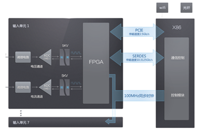
Figure 7 PA power analyzer architecture
Previous article:Rohde & Schwarz's R&S QPS200 device receives TSA certification
Next article:How to quickly test the temperature rise curve of a product
- Popular Resources
- Popular amplifiers
- Keysight Technologies Helps Samsung Electronics Successfully Validate FiRa® 2.0 Safe Distance Measurement Test Case
- From probes to power supplies, Tektronix is leading the way in comprehensive innovation in power electronics testing
- Seizing the Opportunities in the Chinese Application Market: NI's Challenges and Answers
- Tektronix Launches Breakthrough Power Measurement Tools to Accelerate Innovation as Global Electrification Accelerates
- Not all oscilloscopes are created equal: Why ADCs and low noise floor matter
- Enable TekHSI high-speed interface function to accelerate the remote transmission of waveform data
- How to measure the quality of soft start thyristor
- How to use a multimeter to judge whether a soft starter is good or bad
- What are the advantages and disadvantages of non-contact temperature sensors?
- Innolux's intelligent steer-by-wire solution makes cars smarter and safer
- 8051 MCU - Parity Check
- How to efficiently balance the sensitivity of tactile sensing interfaces
- What should I do if the servo motor shakes? What causes the servo motor to shake quickly?
- 【Brushless Motor】Analysis of three-phase BLDC motor and sharing of two popular development boards
- Midea Industrial Technology's subsidiaries Clou Electronics and Hekang New Energy jointly appeared at the Munich Battery Energy Storage Exhibition and Solar Energy Exhibition
- Guoxin Sichen | Application of ferroelectric memory PB85RS2MC in power battery management, with a capacity of 2M
- Analysis of common faults of frequency converter
- In a head-on competition with Qualcomm, what kind of cockpit products has Intel come up with?
- Dalian Rongke's all-vanadium liquid flow battery energy storage equipment industrialization project has entered the sprint stage before production
- Allegro MicroSystems Introduces Advanced Magnetic and Inductive Position Sensing Solutions at Electronica 2024
- Car key in the left hand, liveness detection radar in the right hand, UWB is imperative for cars!
- After a decade of rapid development, domestic CIS has entered the market
- Aegis Dagger Battery + Thor EM-i Super Hybrid, Geely New Energy has thrown out two "king bombs"
- A brief discussion on functional safety - fault, error, and failure
- In the smart car 2.0 cycle, these core industry chains are facing major opportunities!
- Rambus Launches Industry's First HBM 4 Controller IP: What Are the Technical Details Behind It?
- The United States and Japan are developing new batteries. CATL faces challenges? How should China's new energy battery industry respond?
- Murata launches high-precision 6-axis inertial sensor for automobiles
- Ford patents pre-charge alarm to help save costs and respond to emergencies
- About serial port loopback test
- 【ST NUCLEO-G071RB Review】SPI
- SCI Configuration of C2000 LaunchPad
- :Practical Analog Circuit Design Technology-Section 1
- The rice dumplings exchanged for Chip Coins arrived so quickly
- ADC and analog switch issues
- [BearPi-HM Nano, play with Hongmeng "Touch and Go"]-3-HarmonyOS compilation architecture learning record
- #idlemarket# nRF6936 Nordic IOT Sensor Kit Thingy: 52 Bluetooth module nRF52832
- Can NXP's crossover processor RT1052 execute code in RAM?
- What are the consequences of not connecting high-power wireless data transmission equipment to an antenna?

 Follow me Season 2 Episode 1 All Codes
 ST BMS kit solution Battery management system overall solution


 京公网安备 11010802033920号