In this blog post, we will walk through the steps to test switch characteristics under no-load, nominal load, and full-load conditions.

Reference address:Power supply measurement tips (Part 5): Testing power stage switch characteristics
Before you begin, make sure the startup, shutdown, duty cycle, and dead time of all switches, such as MOSFETs and IGBTs, are as expected. Tektronix oscilloscopes include a high-resolution mode that radically increases vertical resolution so startup and shutdown times can be calculated with the highest accuracy.
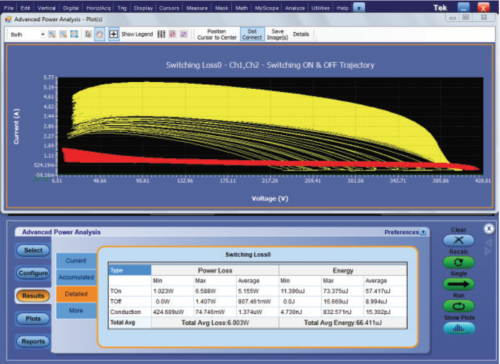
Although almost all components of a power supply experience energy losses, the majority of losses occur when the switching transistor transitions from the off state to the on state (or vice versa). Using the trajectory plots of the start-up losses and turn-off losses for all switching cycles (available in the DPOPWR software), a more complete understanding of switching losses can be obtained, as shown in the figure below.

Switch track map on/off.
At this point, check all VGS signals for noise and glitches. This is an important step because any unexpected glitches on this terminal can cause unwanted startup and shoot-through. To ensure that shoot-through is not possible, check the dead time of the synchronous rectifier or H-bridge.
The timing relationship between the gate drivers and related instrumentation is then verified to ensure it matches the calculations for the design.
To safely measure signals that are not ground referenced, we recommend using a differential probe with the appropriate voltage rating. Be sure not to float the oscilloscope, as this can lead to poor results. You can consider the TDP1000, TDP0500, or P6251 high-voltage differential probe, depending on the application. Each probe implements high-speed, broadband acquisition and measurement capabilities, provides outstanding electrical performance, universal DUT connections, and is easy to use.
It is undoubtedly difficult to measure floating gate signals. We recommend probing the signal at the gate driver input so that you can verify the dead time between the top FET and the bottom FET.
Measuring current at the lowest voltage slew rate can also help you minimize crosstalk and improve accuracy.
Previous article:Power Measurement Tips (Part 4): Debugging Digital and Analog Control Circuits
Next article:Switching loss and conduction loss test (Part 6): Key points of loss test steps
Recommended Content
Latest Test Measurement Articles
- Keysight Technologies Helps Samsung Electronics Successfully Validate FiRa® 2.0 Safe Distance Measurement Test Case
- From probes to power supplies, Tektronix is leading the way in comprehensive innovation in power electronics testing
- Seizing the Opportunities in the Chinese Application Market: NI's Challenges and Answers
- Tektronix Launches Breakthrough Power Measurement Tools to Accelerate Innovation as Global Electrification Accelerates
- Not all oscilloscopes are created equal: Why ADCs and low noise floor matter
- Enable TekHSI high-speed interface function to accelerate the remote transmission of waveform data
- How to measure the quality of soft start thyristor
- How to use a multimeter to judge whether a soft starter is good or bad
- What are the advantages and disadvantages of non-contact temperature sensors?
MoreSelected Circuit Diagrams
MorePopular Articles
- Innolux's intelligent steer-by-wire solution makes cars smarter and safer
- 8051 MCU - Parity Check
- How to efficiently balance the sensitivity of tactile sensing interfaces
- What should I do if the servo motor shakes? What causes the servo motor to shake quickly?
- 【Brushless Motor】Analysis of three-phase BLDC motor and sharing of two popular development boards
- Midea Industrial Technology's subsidiaries Clou Electronics and Hekang New Energy jointly appeared at the Munich Battery Energy Storage Exhibition and Solar Energy Exhibition
- Guoxin Sichen | Application of ferroelectric memory PB85RS2MC in power battery management, with a capacity of 2M
- Analysis of common faults of frequency converter
- In a head-on competition with Qualcomm, what kind of cockpit products has Intel come up with?
- Dalian Rongke's all-vanadium liquid flow battery energy storage equipment industrialization project has entered the sprint stage before production
MoreDaily News
- Allegro MicroSystems Introduces Advanced Magnetic and Inductive Position Sensing Solutions at Electronica 2024
- Car key in the left hand, liveness detection radar in the right hand, UWB is imperative for cars!
- After a decade of rapid development, domestic CIS has entered the market
- Aegis Dagger Battery + Thor EM-i Super Hybrid, Geely New Energy has thrown out two "king bombs"
- A brief discussion on functional safety - fault, error, and failure
- In the smart car 2.0 cycle, these core industry chains are facing major opportunities!
- The United States and Japan are developing new batteries. CATL faces challenges? How should China's new energy battery industry respond?
- Murata launches high-precision 6-axis inertial sensor for automobiles
- Ford patents pre-charge alarm to help save costs and respond to emergencies
- New real-time microcontroller system from Texas Instruments enables smarter processing in automotive and industrial applications
Guess you like
- Last day! TI live broadcast with prizes, ACI motor actual control evaluation example, in-depth understanding of TI C2000
- Here is a Tai Chi Bagua diagram of the radio frequency industry
- [Chuanglong TL570x-EVM] Example project running
- How to download KEIL DFP package experience sharing
- Detailed explanation of the flash encryption principle and steps of ESP32, ESP32S2, and ESP-C3 series
- After the stm32 serial port is initialized, the microcontroller does not run automatically, most likely because printf is used
- STMicroelectronics Industry Summit 2020 invites you to attend!
- EEWORLD University----[High Precision Laboratory] Motor Drive: Motor Drive Technology
- CircuitPython Creative Works
- Infineon Tmall store birthday promotion: triple gifts are offered, purchase designated products over 200 yuan and get a development board worth 500 yuan for free!

 Classic EMI Filter Design Second Edition


 京公网安备 11010802033920号