Not only for the elderly, but also in many other situations, fall alarms are very helpful, especially when people fall from a high place, such as when they are climbing, building, cleaning windows, painting and repairing roofs.
This has prompted people to become more and more interested in the development of fall detection and fall prediction instruments. In recent years, with the development of iMEMS® accelerometer technology, it has become possible to design a fall detector based on a three-axis accelerometer. The basic principle of this fall detector is to sense the changes in the body posture of the individual wearing the instrument by measuring the acceleration changes in three orthogonal directions during exercise, and to determine whether the individual has fallen through algorithm analysis. When an individual falls, the instrument can cooperate with the GPS module and the wireless transmission module to locate and alarm the situation in order to obtain corresponding assistance. The core part of the fall detector is the detection principle and algorithm for determining whether a fall has occurred.
ADXL3451 is a 3-axis, digital output acceleration sensor from ADI. This article will propose a new fall detection solution based on ADXL345 based on the study of the fall detection principle.
iMEMS accelerometer ADXL345
iMEMS semiconductor technology integrates micro-mechanical structures and electronic circuits on the same chip. iMEMS accelerometers use this technology to measure single-axis, dual-axis, or even tri-axis acceleration and generate analog or digital outputs. Depending on the application, the measurement range of the accelerometer ranges from a few g to tens of g. Accelerometers with digital outputs also integrate multiple interrupt modes. These features can provide users with more convenient and flexible solutions.
ADXL345 is a 3-axis, digital output accelerometer based on iMEMS technology recently launched by ADI. ADXL345 has variable measurement ranges of +/-2g, +/-4g, +/-8g, +/-16g; up to 13bit resolution; fixed 4mg/LSB sensitivity; 3mm*5mm*1mm ultra-small package; 40-145uA ultra-low power consumption; standard I2C or SPI digital interface; 32-level FIFO storage; as well as internal multiple motion state detection and flexible interrupt methods. All these features make ADXL345 help greatly simplify the fall detection algorithm, making it an accelerometer very suitable for fall detector applications.
The fall detection solution given in this article is completely based on the motion state detection function and interrupt function inside the ADXL345. It does not even require real-time reading of the specific value of acceleration and complex calculation operations, which can minimize the complexity of the algorithm.
Interrupt system
Figure 1 shows the system block diagram and pin definitions of ADXL345.
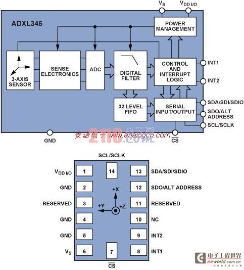
Figure 1 ADXL345 system block diagram and pin definition
ADXL345 has two programmable interrupt pins: Int1 and Int2. As well as Data_Ready, Single_Tap, Double_Tap, Activity, Inactivity, Free_Fall, Watermark, Overrun, a total of 8 interrupt sources. Each interrupt source can be enabled or disabled independently, and you can flexibly choose whether to map to the Int1 or Int2 interrupt pin. All functions can be used at the same time, but some functions may need to share interrupt pins. The interrupt function is enabled or disabled through the corresponding bit of the INT_ENABLE register, and mapped to the Int1 pin or Int2 pin through the corresponding bit of the INT_MAP register. The specific definition of the interrupt function is as follows:
1. Data_Ready When new data is generated, the Data_Ready interrupt is set; when there is no new data, the Data_Ready interrupt is cleared.
2. Single_Tap When the acceleration value exceeds a certain threshold (THRESH_TAP) and the duration is less than a certain time range (DUR), the Single_Tap interrupt is set.
3. Double_Tap When the first Single_Tap event occurs, after a certain time (LATENT), and within a certain time (WINDOW), when a second Single_Tap event occurs, the Double_Tap interrupt is set.
Figure 2 shows the schematic diagram of the effective Single_Tap interrupt and Double_Tap interrupt.
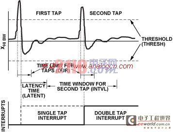
Figure 2 Single_Tap and Double_Tap interrupts
4. Activity When the acceleration value exceeds a certain threshold (THRESH_ACT), the Activity interrupt is set.
5. Inactivity When the acceleration value is lower than a certain threshold (THRESH_INACT) and lasts for more than a certain time (TIME_INACT), the Inactivity interrupt is set. The maximum time that TIME_INACT can be set is 255s.
It should be noted that for Activity and Inactivity interrupts, users can enable or disable them for the X, Y, and Z axes respectively. For example, you can enable only the Activity interrupt for the X axis and disable the Activity interrupts for the Y and Z axes.
In addition, the user can freely select between DC-coupled and AC-coupled operation for Activity and Inactivity interrupts. The difference is that in DC-coupled operation, the acceleration value of each sample point is directly compared with a threshold (THRESH_ACT or THRESH_INACT) to determine whether an interrupt has occurred, while in AC-coupled operation, the acceleration value of each sample point is compared with a threshold (THRESH_ACT or THRESH_INACT) based on the difference between the two samples. Activity detection in AC-coupled operation uses the sample point at the beginning of the test as a reference. The acceleration value of each subsequent sample point is compared with the reference point. If the difference between the two exceeds the threshold (THRESH_ACT), the Activity interrupt is set. In AC-coupled operation, a reference point is also selected for Inctivity detection. If the difference between the acceleration of the new sample point and the reference point exceeds the threshold (THRESH_INACT), the reference point is updated by the sample point. If the acceleration difference between the new sampling point and the reference point is less than the threshold (THRESH_INACT) and lasts for more than a certain time (TIME_INACT), the Inctivity is set.
6. Free_Fall The Free_Fall interrupt is set when the acceleration value is below a certain threshold (THRESH_FF) and lasts for more than a certain time (TIME_FF). The difference between the Free_Fall interrupt and the Inactivity interrupt is that the Free_Fall interrupt is mainly used to detect free fall motion. Therefore, the X, Y, and Z axes are always enabled or disabled at the same time; the time setting is also much smaller than that of the Inactivity interrupt. The maximum value that TIME_FF can be set to is 1.28s; and the Free_Fall interrupt can only work in dc-coupled mode.
7. Watermark When the number of samples stored in the FIFO exceeds a certain number (SAMPLES), the Watermark interrupt is set. When the sample points in the FIFO are read and the number of sample points stored in it is less than the value (SAMPLES), the Watermark interrupt is automatically cleared.
It should be pointed out that the FIFO of ADXL345 can store up to 32 sampling points (X, Y, Z axis values), and has four working modes: Bypass mode, normal FIFO mode, Stream mode, and Trigger mode. The FIFO function is also an important and very useful function of ADXL345. However, the solution given later in this article does not use the FIFO function, so it will not be introduced in detail here.
8. Overrun When a new sampling point updates the previous sampling point that has not been read, the Overrun interrupt is set. The Overrun function is related to the working mode of the FIFO. When the FIFO works in the Bypass mode, if a new sampling point updates the values in the DATAX, DATAY and DATAZ registers, the Overrun interrupt is set. When the FIFO works in the other three modes, the Overrun interrupt is set only when the FIFO is full of 32 points. After the sampling points in the FIFO are read, the Overrun interrupt is automatically cleared.
Acceleration change characteristics during falling
The research on the principle of fall detection mainly focuses on finding the characteristics of acceleration changes of the human body during a fall.
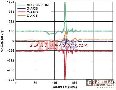
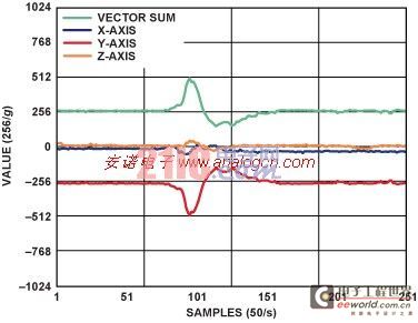
Figure 3 shows the acceleration curves during different movements, including (a) walking upstairs, (b) walking downstairs, (c) sitting down, and (d) standing up. Assume that the fall detector is fixed on the human body being measured. The red curve is the acceleration curve of the Y axis (vertical direction), which should be -1g in the normal static state; the black and yellow curves are the acceleration curves of the X axis (front and back direction) and the Z axis (left and right direction), respectively, which should be 0g in the normal static state; the green curve is the vector sum of the three-axis acceleration, which should be +1g in the normal static state.
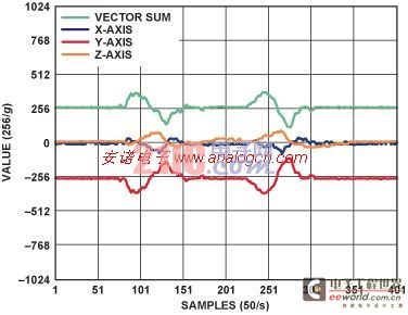
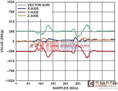
a. Walk upstairs b. Walk downstairs
c. sit down d. stand up
Figure 3 Acceleration curves during different motion processes
Since the elderly move relatively slowly, the acceleration changes will not be very large during normal walking. The most obvious acceleration change is a spike of more than 3g on the Y-axis acceleration (and the acceleration vector sum) during the sitting action, which is caused by the contact between the body and the chair.
The acceleration change during a fall is completely different. Figure 4 shows the acceleration change curve during an accidental fall. By comparing Figure 4 with Figure 3, it can be found that there are four main characteristics of acceleration change during a fall, which can be used as a criterion for fall detection. These four characteristics are marked with red boxes in Figure 4, and they will be introduced in detail one by one below.
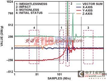
Figure 4 Acceleration curve during falling
1. Weightlessness: At the beginning of a fall, there will be a certain degree of weightlessness. During the free fall, this phenomenon will be more obvious, and the vector sum of acceleration will drop to close to 0g. The duration is related to the height of the free fall. For a general fall, although the weightlessness phenomenon will not be as obvious as a free fall, the total acceleration will be less than 1g (normally the total acceleration should be greater than 1g). Therefore, this can be used as the first basis for judging the fall state. It can be detected by the Free_Fall interrupt of ADXL345.
2. Impact: After weightlessness, when a person falls, he or she will collide with the ground or other objects, which will produce a large impact in the acceleration curve. This impact can be detected by the Activity interrupt of ADXL345. Therefore, the Activity interrupt generated immediately after the Free_Fall interrupt is the second basis for judging the fall state.
3. Stillness: Usually, after a person falls, that is, after a collision, it is impossible for the person to get up immediately, and there will be a short period of stillness (if the person falls into a coma, it may even be stillness for a longer period of time). This is reflected in the acceleration curve as a period of stability. This can be detected by the Inactivity interrupt of ADXL345. Therefore, the Inactivity interrupt after the Activity interrupt is the third basis for judging the fall state.
4. Compare with the initial state: After falling, the human body will flip over, so the direction of the human body will be different from the original static standing posture (initial state). This makes the three-axis acceleration values in the static state after falling different from the three-axis acceleration in the initial state (see Figure 4). Assuming that the fall detector is fixed to a certain part of the human body being tested, the three-axis acceleration values in the initial state can be considered known (in this example, the initial state is: X axis 0g, Y axis -1g, Z axis 0g). Read the three-axis acceleration data after the Inactivity interruption and compare it with the initial state. As shown in Figure 4, the direction of gravity acceleration changes from -1g on the Y axis to 1g on the Z axis, which means that the human body has fallen sideways. Therefore, the fourth basis for fall detection is that the acceleration value in the static state after falling changes from the initial state, and the vector change exceeds a certain threshold value (such as 0.7g).
These four judgment bases are combined to form the entire fall detection algorithm, which can give an alarm for the fall state. Of course, it is also necessary to pay attention to the time interval between each interruption to be within a reasonable range. For example, unless you fall from a very high building, the time interval between the Free_Fall interruption (weightlessness) and the Activity interruption (impact) will not be very long. Similarly, under normal circumstances, the time interval between the Activity interruption (impact) and the Inactivity interruption (stillness) will not be very long. This article will then give a set of reasonable values through a specific example. Of course, the detection threshold and time parameters of the relevant interruption can also be flexibly set according to needs.
In addition, if the fall has serious consequences, such as causing a person to fall into a coma, the human body will remain motionless for a longer period of time. This state can still be detected by the Inactivity interrupt. In other words, if it is found that the Inactivity state remains for a long time after the fall, a serious alarm can be given again.
Typical circuit connection
The circuit connection between ADXL345 and microcontroller is very simple. The test platform in this article consists of ADXL345 and microcontroller ADuC70262. Figure 5 shows the typical circuit connection between ADXL345 and ADuC70262. The CS pin of ADXL345 is connected to a high level, indicating that ADXL345 works in I2C mode. SDA and SCL are the data line and clock line of the I2C bus, which are connected to the corresponding I2C bus pins of ADuC7026 respectively. A GPIO pin of ADuC7026 is connected to the ALT pin of ADXL345 to select the I2C address of ADXL345. The INT1 pin of ADXL345 is connected to the IRQ input of ADuC7026 to generate an interrupt signal.
Other microcontrollers or processors can be connected to the ADXL345 using a circuit similar to Figure 5. The ADXL345 can also operate in SPI mode to achieve a higher data transfer rate. For a detailed description of the SPI operating mode, please refer to the ADXL345 data sheet.
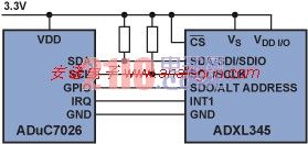
Figure 5 Typical circuit connection between ADXL345 and microcontroller
Table 1 ADXL345 register function description
Address Register Name Type Default Value Description Setting Value Setting Function
0DEVID Read only 0xE5 Device ID Read only
1-1CReserved Reserved, do not operate the reserved
1DTHRESH_TAP Read/write 0x00Tap threshold is not used
1EOFSX Read/Write 0x00 X-axis offset 0x06 Compensate for X-axis offset, obtained by initialization correction
1FOFSY Read/Write 0x00 Y-axis offset 0xF9 Compensate for Y-axis offset, obtained by initialization correction
20OFSZ Read/Write 0x00 Z-axis offset 0xFC Compensate for Z-axis offset, obtained by initialization correction
21DUR Read/write 0x00Tap duration not used
22LATENT read/write 0x00Tap delay time is not used
23WINDOW read/write 0x00Tap time window is not used
24THRESH_ACT Read/write 0x00 Activity threshold 0x20/0x08 Set Activity threshold to 2g or 0.5g
25THRESH_INACT Read/write 0x00 Inactivity threshold 0x03 Set the Inactivity threshold to 0.1875g
26TIME_INACT Read/write 0x00 Inactivity time 0x02/0x0A Set the Inactivity time to 2s or 10s
27ACT_INACT_CTL Read/write 0x00 Activity/Inactivity enable control 0x7F/0xFF Enables Activity and Inactivity functions for the X, Y, and Z axes. Inactivity is in AC coupled mode, and Activity is in DC coupled or AC coupled mode.
28THRESH_FF Read/write 0x00 Free-Fall threshold 0x0C Set the Free-Fall threshold to 0.75g
29TIME_FF Read/write 0x00 Free-Fall time 0x06 Set the Free-Fall time to 30ms
2ATAP_AXES Read/Write 0x00 Tap/Double Tap Enable Control Not Used
2BACT_TAP_STATUS Read only 0x00 Activity/Tap interrupt axis indication Read only
2CBW_RATE Read/write 0x0A Sampling rate and power mode control 0x0A Set sampling rate to 100Hz
2DPOWER_CTL Read/write 0x00 Working mode control 0x00 Set to normal working mode
2EINT_ENABLE Read/write 0x00 Interrupt enable control 0x1C Enable Activity, Inactivity, Free-Fall interrupts
2FINT_MAP read/write 0x00 interrupt mapping control 0x00 all interrupts are mapped to Int1 pin
30INT_SOURCE Read only 0x00 Interrupt source indication Read only
31DATA_FORMAT Read/write 0x00 Data format control 0x0B Set to +/-16g measurement range, 13bit right-aligned mode, interrupt is high level trigger, use I2C data interface
32DATAX0 read only 0x00X axis data read only
33DATAX1 read only 0x00 read only
34DATAY0 Read only 0x00 Y axis data read only
35DATAY1 Read only 0x00 Read only
36DATAZ0 Read only 0x00Z axis data read only
37DATAZ1 Read only 0x00 Read only
38FIFO_CTL read/write 0x00FIFO control not used
39FIFO_STATUS Read only 0x00FIFO status not used
Simplifying the Fall Detection Algorithm Using the ADXL345
This section will give the specific algorithm implementation of the above solution. Table 1 briefly describes the role of each register and the setting value in this algorithm. For the specific meaning of each bit in each register, please refer to the ADXL345 data sheet.
It should be noted that in the setting values given in Table 1, some registers will give two values, which means that these two values will be switched in the algorithm to achieve different detection purposes. The flowchart of the algorithm is shown in Figure 6.
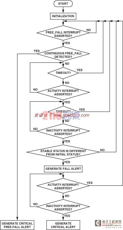
Figure 6 Algorithm flow chart
In the algorithm, the settings of thresholds and time parameters for various interruptions are described as follows.
1. After initialization, the system waits for the Free_Fall interrupt (weightlessness), where THRESH_FF is set to 0.75g and TIME_FF is set to 30ms.
2. After the Free_Fall interrupt is generated, the system starts waiting for the Activity interrupt (impact). Here, THRESH_ACT is set to 2g and the Activity interrupt is in DC coupled mode.
3. The time interval between Free_Fall interrupt (weightlessness) and Activity interrupt (impact) is set to 200ms. If it exceeds 200ms, it is considered invalid. The 200ms timing needs to be implemented by the timer in the MCU.
4. After the Activity interrupt is generated, the system starts waiting for the Inactivity interrupt (inactivity after impact). Here, THRESH_INACT is set to 0.1875 g, TIME_INACT is set to 2 s, and the Inactivity interrupt is in ac-coupled mode.
5. Within 3.5s after the Activity interrupt (impact) is generated, an Inactivity interrupt (inactivity after impact) should be generated. If it times out, it is considered invalid. The 3.5s timing needs to be implemented by the timer in the MCU.
6. If the vector difference between the acceleration value after the Inactivity interruption and the value in the initial state (assuming it is known) exceeds 0.7g, it means that a valid fall is detected and the system will issue an alarm.
7. After a fall is detected, the Activity interrupt and Inactivity interrupt are checked to determine if the person has been motionless for a long time after the fall. Here, THRESH_ACT is set to 0.5g, and the Activity interrupt is in ac-coupled mode. THRESH_INACT is set to 0.1875g, TIME_INACT is set to 10s, and the Inactivity interrupt is in ac-coupled mode. In other words, if the person does not move for 10s, an Inactivity interrupt is generated, causing the system to issue a critical alarm. If the person moves during this period, an Activity interrupt is generated, ending the entire judgment process.
8. This algorithm can also detect a person falling from a higher place. If Free_Fall interrupts occur continuously and the interval between them is less than 100ms, it can be considered that the person is in a continuous falling state. If Free_Fall interrupts (weightlessness) occur continuously for 300ms, it means that the person has fallen from a height of more than 0.45m, and the system will give a fall alarm.

This algorithm has been implemented in the ADuC7026 microcontroller in C language (see Appendix). This paper designed an experimental scheme to verify the algorithm. The experiment conducted 10 tests on different falling postures such as falling forward, falling backward, falling to the left and right sides, and whether there was a long period of rest after falling. The relevant test results are given in Table 2.
Table 2 Test results
Falling posture Long-term immobility after falling 12345678910
Fall forward or PPPPPPP
It's P*P*P*P*P*P*P*P*P*
Falling backwards PPPPPPPPPP
It's P*P*P*P*P*P*P*P*P*
Fall to the left side PPPPPPPPPP
It's P*P*P*P*P*P*P*P*P*
Fall to the right side PPPPPPPPPP
It's P*P*P*P*P*P*P*P*P*
Note: The symbol √ indicates that a fall is detected, and the symbol * indicates that a long period of inactivity after a fall is detected.
Note: The symbol √ indicates that a fall is detected, and the symbol * indicates that a long period of inactivity after a fall is detected.
From this experiment, we can see that the solution based on ADXL345 can effectively detect the fall state. Of course, this is just a simple experimental scheme, and more comprehensive, effective and long-term experiments are still needed to verify the reliability of this solution.
in conclusion
ADXL345 is a powerful acceleration sensor product from ADI. This article proposes a new fall detection solution by using the multiple motion state detection functions and flexible interrupt functions inside ADXL345. It has been verified that this solution has the advantages of low algorithm complexity and high detection accuracy.
Previous article:Application range of ultrasonic sensors
Next article:Micro Load Cell Technology
- Keysight Technologies Helps Samsung Electronics Successfully Validate FiRa® 2.0 Safe Distance Measurement Test Case
- From probes to power supplies, Tektronix is leading the way in comprehensive innovation in power electronics testing
- Seizing the Opportunities in the Chinese Application Market: NI's Challenges and Answers
- Tektronix Launches Breakthrough Power Measurement Tools to Accelerate Innovation as Global Electrification Accelerates
- Not all oscilloscopes are created equal: Why ADCs and low noise floor matter
- Enable TekHSI high-speed interface function to accelerate the remote transmission of waveform data
- How to measure the quality of soft start thyristor
- How to use a multimeter to judge whether a soft starter is good or bad
- What are the advantages and disadvantages of non-contact temperature sensors?
- Innolux's intelligent steer-by-wire solution makes cars smarter and safer
- 8051 MCU - Parity Check
- How to efficiently balance the sensitivity of tactile sensing interfaces
- What should I do if the servo motor shakes? What causes the servo motor to shake quickly?
- 【Brushless Motor】Analysis of three-phase BLDC motor and sharing of two popular development boards
- Midea Industrial Technology's subsidiaries Clou Electronics and Hekang New Energy jointly appeared at the Munich Battery Energy Storage Exhibition and Solar Energy Exhibition
- Guoxin Sichen | Application of ferroelectric memory PB85RS2MC in power battery management, with a capacity of 2M
- Analysis of common faults of frequency converter
- In a head-on competition with Qualcomm, what kind of cockpit products has Intel come up with?
- Dalian Rongke's all-vanadium liquid flow battery energy storage equipment industrialization project has entered the sprint stage before production
- Allegro MicroSystems Introduces Advanced Magnetic and Inductive Position Sensing Solutions at Electronica 2024
- Car key in the left hand, liveness detection radar in the right hand, UWB is imperative for cars!
- After a decade of rapid development, domestic CIS has entered the market
- Aegis Dagger Battery + Thor EM-i Super Hybrid, Geely New Energy has thrown out two "king bombs"
- A brief discussion on functional safety - fault, error, and failure
- In the smart car 2.0 cycle, these core industry chains are facing major opportunities!
- The United States and Japan are developing new batteries. CATL faces challenges? How should China's new energy battery industry respond?
- Murata launches high-precision 6-axis inertial sensor for automobiles
- Ford patents pre-charge alarm to help save costs and respond to emergencies
- New real-time microcontroller system from Texas Instruments enables smarter processing in automotive and industrial applications
- STM32F103 brushless DC motor control program
- [GD32E231 DIY Contest] Part 2: Dynamic QR Code Display
- EEWORLD University ----PI power chip: Learn about BridgeSwitch in one minute
- CCS compilation optimization and volatile
- cc3200 GPIO input mode error
- Excellent materials, free of credits: Album of routines for common functional modules in the National Undergraduate Electronic Design Competition
- [Popular Science] IGBT - Starting from the name
- Relay protection device tester verification
- The circuit board cannot start normally after plugging in a power bank
- FPGA beginners ask for help with Verilog test code

 Good stuff doesn’t wait for anyone, so hurry up and download it!


 京公网安备 11010802033920号