The oldest and most classic trigger - the inspiration brought to us by edge trigger
Edge triggering has been inseparable from oscilloscopes since their birth. The earliest analog oscilloscopes only had one trigger function, which is edge triggering. Edge triggering is very simple and commonly used, so many engineers have used oscilloscopes for several years without realizing that it is a trigger function. Edge triggering includes rising edge triggering and falling edge triggering. Taking rising edge triggering as an example, the trigger of the oscilloscope will compare the voltages of the two points before and after the trigger level (Trigger Level). When the voltage of the latter point is higher than the former point, it will be judged as a rising edge trigger; the opposite is true for falling edge triggering.
Measuring the maximum/minimum voltage (Max/Min) of a signal is a common measurement item. There are two commonly used methods. One is to use the automatic measurement of the oscilloscope directly, turn on the statistics function, and find the maximum/minimum value. The second is to turn on the infinite afterglow of the oscilloscope, accumulate for a period of time, and then use the cursor to measure the maximum/minimum value. However, both methods have a small disadvantage, that is, it is impossible to intuitively see the waveform corresponding to the Max/Min voltage. For debugging, it is more desirable to clearly see the worst waveform so as to find debugging ideas. Using traditional edge triggering, by adjusting the trigger level of the edge trigger, we can easily see the waveform corresponding to the maximum/minimum voltage and measure it.
Select rising edge trigger and set the trigger mode to Normal (Note 1). Then slowly increase the trigger level until the trigger event becomes very rare (the on/off interval of the Trig'd green indicator on the oscilloscope panel becomes significantly longer or the screen waveform refresh speed becomes significantly slower), which means that the voltage rise is at the limit position, and the waveform at the trigger point is the waveform of the maximum voltage. Similarly, select falling edge trigger and lower the trigger level to accurately locate the waveform corresponding to the minimum voltage.
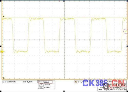
Figure 1: When measuring, the trigger level is usually at 50% of the peak-to-peak value, making it difficult to trigger the waveform corresponding to the maximum/minimum voltage
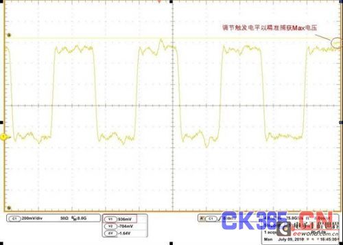
Figure 2: By adjusting the trigger level, the maximum voltage can be clearly seen.
Tips for Setup/Hold Time Measurements
Setup/hold time measurement is a very troublesome project. This measurement is too random. You may get a very good result this time, but the next time you measure it, it may be far beyond the specification. What test engineers are most worried about is that their measured results are inconsistent with the customer's measurement results and are questioned. How can they find the worst condition as the measurement result and leave the customer speechless? Many engineers use the method of repeating the measurement several times and taking the worst value as the measurement result. This limited enumeration method has certain desirability, but it is still very random. A better way is to use the setup/hold time violation trigger function of the Tektronix oscilloscope to directly find the worst setup/hold time. It can not only greatly save measurement time, but also ensure the persuasiveness of the measurement results. [page]
The principle of setup/hold trigger of Tektronix oscilloscope is that when the trigger detects a violation of setup time or hold time of the data signal (less than the set value), the oscilloscope will trigger. When we need to measure setup time, set the hold time limit to 0 (to ensure that the hold time will not be violated), slowly lower the setup time limit, and when the trigger event becomes rare, the worst setup time can be located, and then we can measure. Similarly, when measuring hold time, set the setup time limit to 0, and adjust the hold time limit to locate the worst hold time.
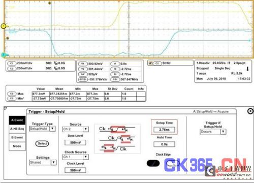
Figure 3: Setup/Hold trigger is a great aid in measuring setup/hold time
Another way to measure rise/fall time
The measurement of rise/fall time can also be assisted by triggering to intuitively see the waveform with the worst rise/fall time. Select the trigger mode as Transition trigger, enter the low voltage and high voltage values, and select the trigger condition as "Greater Than", that is, trigger when the transition edge time is greater than the set value. Then slowly increase the set value until the trigger event becomes rare, and you can accurately trigger the waveform with the largest rise/fall time.
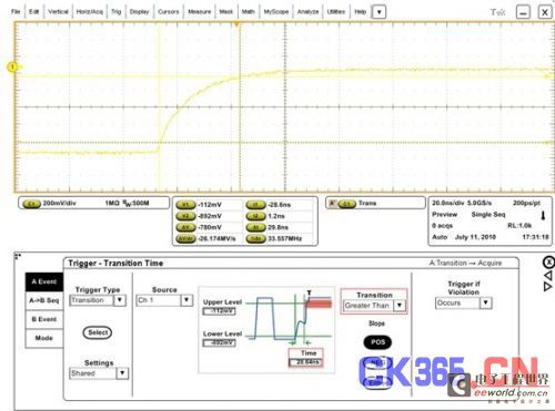
Figure 4: Using edge time triggering to locate the worst rise/fall time waveform
Finding long pattern events in high-speed serial buses
The code patterns in high-speed serial buses are complex and changeable. Different code patterns often have different signal characteristics. For example, at the receiving end, the voltage amplitude of the transition bit is often low, while the amplitude of the non-transition bit is high. Too long continuous 1 or continuous 0 may cause voltage drops. Sometimes we hope to observe and measure the status of some specific code patterns, such as the code pattern when there are more than 4 consecutive "1" or "0". At this time, we can use the pulse width trigger (Pulse Width Trigger) or the timeout trigger (Timeout Trigger) to locate the code pattern of interest.
The so-called pulse width trigger means setting the upper and lower limits of the pulse width respectively. When the pulse width is between the upper and lower limits, the oscilloscope will trigger. Taking the PCI-E generation 2.5Gbps signal as an example, when we want to trigger more than 4 consecutive "1", we can set a lower limit (such as 1.4ns) that is less than 1.6ns (the standard pulse width of 4 bits in a row) and greater than 1.2ns (the standard pulse width of 3 bits in a row), set an upper limit greater than 1.6ns, and select the positive pulse as the pulse type, and then it can be accurately triggered. The timeout trigger is similar to the pulse width trigger, the difference is that the timeout trigger only needs to set the lower limit of the width, without setting the upper limit. In this example, both triggering methods are feasible.
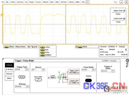
Figure 5 Using pulse width trigger to locate long "1" pattern
Previous article:How to distinguish between analog bandwidth and digital real-time bandwidth of oscilloscope
Next article:Application of Tektronix Mixed Domain Oscilloscope in Embedded Systems with Wireless Function
- Popular Resources
- Popular amplifiers
- Keysight Technologies Helps Samsung Electronics Successfully Validate FiRa® 2.0 Safe Distance Measurement Test Case
- From probes to power supplies, Tektronix is leading the way in comprehensive innovation in power electronics testing
- Seizing the Opportunities in the Chinese Application Market: NI's Challenges and Answers
- Tektronix Launches Breakthrough Power Measurement Tools to Accelerate Innovation as Global Electrification Accelerates
- Not all oscilloscopes are created equal: Why ADCs and low noise floor matter
- Enable TekHSI high-speed interface function to accelerate the remote transmission of waveform data
- How to measure the quality of soft start thyristor
- How to use a multimeter to judge whether a soft starter is good or bad
- What are the advantages and disadvantages of non-contact temperature sensors?
- Innolux's intelligent steer-by-wire solution makes cars smarter and safer
- 8051 MCU - Parity Check
- How to efficiently balance the sensitivity of tactile sensing interfaces
- What should I do if the servo motor shakes? What causes the servo motor to shake quickly?
- 【Brushless Motor】Analysis of three-phase BLDC motor and sharing of two popular development boards
- Midea Industrial Technology's subsidiaries Clou Electronics and Hekang New Energy jointly appeared at the Munich Battery Energy Storage Exhibition and Solar Energy Exhibition
- Guoxin Sichen | Application of ferroelectric memory PB85RS2MC in power battery management, with a capacity of 2M
- Analysis of common faults of frequency converter
- In a head-on competition with Qualcomm, what kind of cockpit products has Intel come up with?
- Dalian Rongke's all-vanadium liquid flow battery energy storage equipment industrialization project has entered the sprint stage before production
- Allegro MicroSystems Introduces Advanced Magnetic and Inductive Position Sensing Solutions at Electronica 2024
- Car key in the left hand, liveness detection radar in the right hand, UWB is imperative for cars!
- After a decade of rapid development, domestic CIS has entered the market
- Aegis Dagger Battery + Thor EM-i Super Hybrid, Geely New Energy has thrown out two "king bombs"
- A brief discussion on functional safety - fault, error, and failure
- In the smart car 2.0 cycle, these core industry chains are facing major opportunities!
- The United States and Japan are developing new batteries. CATL faces challenges? How should China's new energy battery industry respond?
- Murata launches high-precision 6-axis inertial sensor for automobiles
- Ford patents pre-charge alarm to help save costs and respond to emergencies
- New real-time microcontroller system from Texas Instruments enables smarter processing in automotive and industrial applications
- Lingdongwei MM32 series MDK5 project from 0 to 1
- SD8906A_600aA 1.5MHz Synchronous
- i.MX RT port of openmv
- CLUE badge
- The I/O of this MCU is the kind that cannot be seen.
- The problem of interference between ADC channels of STM32
- Can't the RTC of MSP430F6723 use the internal clock REFOCLK?
- iTOP3399 development board GPIO subsystem - application layer control GPIO
- Has anyone used the ILI6485 display driver IC? I need to use this chip as an RGB driver, but the manufacturer did not provide any information.
- Where does the chip's power come from?

 Multisim Circuit System Design and Simulation Tutorial


 京公网安备 11010802033920号