Traditional mechanical energy meters measure electricity with a meter driven by an aluminum disk driven by magnetic torque. This metering method has many defects such as short life, large error, regular debugging, easy electricity theft, on-site meter reading, etc. The reliability of operation is not guaranteed, and it brings great difficulties to the construction, planning and analysis of urban power grids. In order to solve the above problems, electronic energy meters with anti-electricity theft function, LCD display, infrared communication and 485 communication are gradually being used and will gradually become the mainstream of the market.
System composition
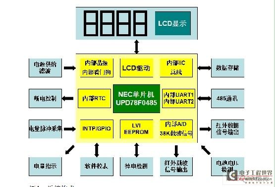
The system structure of the one-way payment rate meter with software calibration function is shown in Figure 1. The implementation principle is: the current and voltage signals of the power grid are sampled by the sampling chip through the shunt, and output to the single-chip microcomputer in the form of pulses (CF). The single-chip microcomputer collects and analyzes the high-frequency pulse CF of electric energy, outputs the electric energy indication pulse signal for the pulse lamp and the meter calibration, and uses the CF signal to calculate the collected electric quantity, send it to the LCD driver, display it on the LCD, and write it to the EEPROM at the same time; in addition to storing the electric quantity information, the EEPROM also has information such as the meter number, which can be read and set through infrared and 485 communication, and can also be displayed on the LCD.
Hardware Design
The hardware design is shown in Figure 1, which is divided into clock supply module, data storage module, pulse acquisition module, software meter calibration module, power-off detection module, infrared output module, 485 communication module, battery voltage detection module, and switch control module. The main control chip uses NEC single-chip microcomputer UPD78F0485, and its basic characteristics are as follows: 1.8" 5.5V wide voltage power supply; internal integrated PLL phase-locked loop crystal oscillator circuit, temperature drift is very small; low power consumption, when the sub-clock is working, the power consumption is as low as 1uA; internal integrated power-on reset circuit and low voltage detection circuit, convenient for power-off data storage; internal integrated A/D, can be used for battery voltage detection; edge-triggered external interrupt, can collect power pulses; internal integrated IIC circuit and two UART circuits, convenient for 2-way communication; and integrated 2 16-bit timers, 2 8-bit timers, and many general I/O ports. These resources are the important reasons why UPD78F0485 is used to design electric energy meters.
The following is a brief analysis of the design of some major hardware circuits in the electric energy meter.
1) 485 communication circuit design:
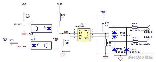
In the electric energy meter system, the meter reading system has only fixed centralized methods when reading the meter: 485, carrier, infrared. 485 is the most widely used method for meter reading due to its low cost, reliable operation, and fast meter reading speed. Figure 2 shows the basic structure of the 485 circuit. This circuit uses an optical coupler to isolate the signal output by the microcontroller and output it to the 3085 chip, which then converts the signal into a differential signal and sends it to the bus. The received signal must also be sent back to the microcontroller through optical coupler isolation. The characteristic of this circuit is that the RE and DE pins of the 3085 are controlled by one lead, saving an I/O port of the microcontroller. This connection method is conditional, that is, the communication on the electric energy meter is not absolutely full-duplex. Since the differential signal transmission distance of the 485 circuit is relatively long and the general wiring environment is relatively harsh, the 485 line must have a varistor for high voltage protection, and a TVS tube to prevent transient high voltage interference and lightning strikes. [page]
2) Infrared communication circuit structure:
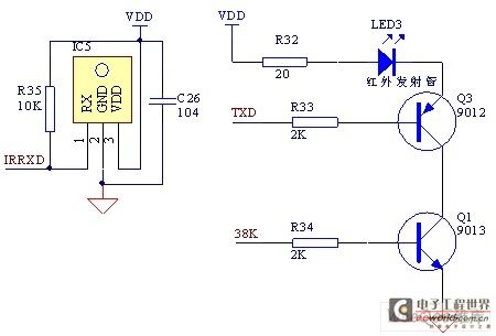
Infrared communication circuits are widely used in electric meters because the infrared handheld meter reading method is still used in many areas. Driven by this market demand, it is necessary for the microcontroller to have two UART ports for communication. As shown in Figure 3, in the infrared transmission circuit, two transistors are superimposed, where the TXD network is used to send data signals and the 38K network is used to send carrier signals. In this way, due to the logic and function of the hardware circuit, LED3 sends out the expected data. This circuit is just a connection method for the infrared transmission circuit. It is also possible to use a transistor to perform the AND operation of TXD and 38K in the program.
3) Metering circuit:
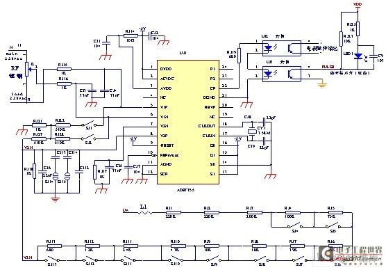
Figure 4: Structure of metering circuit
The metering circuit has ADE7755 as a sampling chip. It collects voltage and current through the shunt, which is the manganese pain chip in the figure, calculates it internally into active power, and then outputs it in the form of pulses (CF). The microcontroller collects this pulse and calculates the power. The many resistors at the bottom of the figure constitute the precision adjustment circuit of the meter.
Software design
The meter operation state is divided into normal state and low power state. An idle flag is set in the program. When the power is off, the idle flag is set to 1. The main program continuously detects this flag. When this flag is set to 1, it enters the sleep state to reduce power consumption.
The realization of software functions is completed by various subroutines, mainly composed of infrared communication subroutines, 485 communication subroutines, software calibration subroutines, power calculation subroutines, power-off processing subroutines, etc. The main program flow chart is shown in Figure 5.
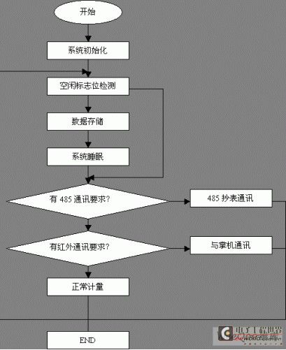
Figure 5: Main program software flow chart
In this system, the main programs are concentrated in initialization, UART communication and software calibration, which are briefly introduced here. [page]
1) Initialization program:
NEC single-chip microcomputer UPD78F0485 itself has rich internal resources, which can greatly reduce the number of peripheral devices, thus reducing the probability of failure. The places that need to be initialized are: internal RAM, option bytes, interrupt control register, serial port control register, timer control register, LVI circuit control register, watchdog control register, IIC circuit control register, LCD driver control register, etc.
2) UART transceiver program:
UART transceiver is completed by the serial port module built into the single-chip microcomputer. In the program, we only need to query the transceiver completion flag, continuous transceiver, error flag detection and error correction. It greatly simplifies the program running process and reduces the pressure of program timing.
3) Software calibration program:
The process of software calibration is as follows: We collect pulses, collect high-frequency pulses output by ADE7755, and the number of high-frequency pulses output for 1 kWh is an integer multiple of the low-frequency pulses. The process of software calibration is to adjust the number of high-frequency pulses corresponding to 1 kWh through serial communication, so as to achieve the purpose of accurate measurement. Design specification format
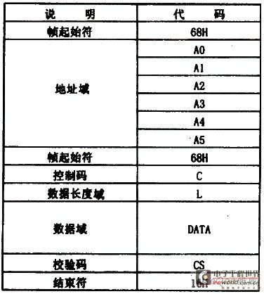
of communication protocol : Figure 6: Byte format Figure 7: Frame format Byte transmission format: 0 (1 start bit) XXXXXXXX (8 data bits) 1 (1 end bit), the idle gap allowed for each byte during data transmission is Communication baud rate: 1200 baud. 3 to 5 FEH as synchronization header, a 16H end word. For detailed command format and technical bureau return format, please refer to 645 specification (DL/T 645-1997). Frame format, as shown in Figure 7. During communication, if no response frame is received within the time limit, it is considered that the transmission is wrong and the previous command frame is resent. Resend up to 3 times. If the response frame is still not received after 3 resends, the corresponding fault prompt information is issued. Conclusion From the above, it can be seen that the paid rate meter designed based on NEC single-chip microcomputer UPD78F0485 fully complies with the national standard GN/T15284-2002 for multi-rate electricity meters and the communication protocol DL/T645-1997 for multi-function electricity meters, and has the characteristics of reasonable functions, low failure rate, few peripheral devices, high measurement accuracy, etc., and greatly saves hardware costs and enhances the feasibility of market promotion. In addition, the compilation environment that supports C language has shortened the development cycle for the actual development of this meter.

Reference address:Design of single-phase multi-rate electric energy meter with software calibration function
System composition
The system structure of the one-way payment rate meter with software calibration function is shown in Figure 1. The implementation principle is: the current and voltage signals of the power grid are sampled by the sampling chip through the shunt, and output to the single-chip microcomputer in the form of pulses (CF). The single-chip microcomputer collects and analyzes the high-frequency pulse CF of electric energy, outputs the electric energy indication pulse signal for the pulse lamp and the meter calibration, and uses the CF signal to calculate the collected electric quantity, send it to the LCD driver, display it on the LCD, and write it to the EEPROM at the same time; in addition to storing the electric quantity information, the EEPROM also has information such as the meter number, which can be read and set through infrared and 485 communication, and can also be displayed on the LCD.

Hardware Design
The hardware design is shown in Figure 1, which is divided into clock supply module, data storage module, pulse acquisition module, software meter calibration module, power-off detection module, infrared output module, 485 communication module, battery voltage detection module, and switch control module. The main control chip uses NEC single-chip microcomputer UPD78F0485, and its basic characteristics are as follows: 1.8" 5.5V wide voltage power supply; internal integrated PLL phase-locked loop crystal oscillator circuit, temperature drift is very small; low power consumption, when the sub-clock is working, the power consumption is as low as 1uA; internal integrated power-on reset circuit and low voltage detection circuit, convenient for power-off data storage; internal integrated A/D, can be used for battery voltage detection; edge-triggered external interrupt, can collect power pulses; internal integrated IIC circuit and two UART circuits, convenient for 2-way communication; and integrated 2 16-bit timers, 2 8-bit timers, and many general I/O ports. These resources are the important reasons why UPD78F0485 is used to design electric energy meters.

The following is a brief analysis of the design of some major hardware circuits in the electric energy meter.
1) 485 communication circuit design:
In the electric energy meter system, the meter reading system has only fixed centralized methods when reading the meter: 485, carrier, infrared. 485 is the most widely used method for meter reading due to its low cost, reliable operation, and fast meter reading speed. Figure 2 shows the basic structure of the 485 circuit. This circuit uses an optical coupler to isolate the signal output by the microcontroller and output it to the 3085 chip, which then converts the signal into a differential signal and sends it to the bus. The received signal must also be sent back to the microcontroller through optical coupler isolation. The characteristic of this circuit is that the RE and DE pins of the 3085 are controlled by one lead, saving an I/O port of the microcontroller. This connection method is conditional, that is, the communication on the electric energy meter is not absolutely full-duplex. Since the differential signal transmission distance of the 485 circuit is relatively long and the general wiring environment is relatively harsh, the 485 line must have a varistor for high voltage protection, and a TVS tube to prevent transient high voltage interference and lightning strikes. [page]

2) Infrared communication circuit structure:
Infrared communication circuits are widely used in electric meters because the infrared handheld meter reading method is still used in many areas. Driven by this market demand, it is necessary for the microcontroller to have two UART ports for communication. As shown in Figure 3, in the infrared transmission circuit, two transistors are superimposed, where the TXD network is used to send data signals and the 38K network is used to send carrier signals. In this way, due to the logic and function of the hardware circuit, LED3 sends out the expected data. This circuit is just a connection method for the infrared transmission circuit. It is also possible to use a transistor to perform the AND operation of TXD and 38K in the program.
3) Metering circuit:

Figure 4: Structure of metering circuit
The metering circuit has ADE7755 as a sampling chip. It collects voltage and current through the shunt, which is the manganese pain chip in the figure, calculates it internally into active power, and then outputs it in the form of pulses (CF). The microcontroller collects this pulse and calculates the power. The many resistors at the bottom of the figure constitute the precision adjustment circuit of the meter.
Software design
The meter operation state is divided into normal state and low power state. An idle flag is set in the program. When the power is off, the idle flag is set to 1. The main program continuously detects this flag. When this flag is set to 1, it enters the sleep state to reduce power consumption.
The realization of software functions is completed by various subroutines, mainly composed of infrared communication subroutines, 485 communication subroutines, software calibration subroutines, power calculation subroutines, power-off processing subroutines, etc. The main program flow chart is shown in Figure 5.

Figure 5: Main program software flow chart
In this system, the main programs are concentrated in initialization, UART communication and software calibration, which are briefly introduced here. [page]
1) Initialization program:
NEC single-chip microcomputer UPD78F0485 itself has rich internal resources, which can greatly reduce the number of peripheral devices, thus reducing the probability of failure. The places that need to be initialized are: internal RAM, option bytes, interrupt control register, serial port control register, timer control register, LVI circuit control register, watchdog control register, IIC circuit control register, LCD driver control register, etc.
2) UART transceiver program:
UART transceiver is completed by the serial port module built into the single-chip microcomputer. In the program, we only need to query the transceiver completion flag, continuous transceiver, error flag detection and error correction. It greatly simplifies the program running process and reduces the pressure of program timing.
3) Software calibration program:
The process of software calibration is as follows: We collect pulses, collect high-frequency pulses output by ADE7755, and the number of high-frequency pulses output for 1 kWh is an integer multiple of the low-frequency pulses. The process of software calibration is to adjust the number of high-frequency pulses corresponding to 1 kWh through serial communication, so as to achieve the purpose of accurate measurement. Design specification format
of communication protocol : Figure 6: Byte format Figure 7: Frame format Byte transmission format: 0 (1 start bit) XXXXXXXX (8 data bits) 1 (1 end bit), the idle gap allowed for each byte during data transmission is Communication baud rate: 1200 baud. 3 to 5 FEH as synchronization header, a 16H end word. For detailed command format and technical bureau return format, please refer to 645 specification (DL/T 645-1997). Frame format, as shown in Figure 7. During communication, if no response frame is received within the time limit, it is considered that the transmission is wrong and the previous command frame is resent. Resend up to 3 times. If the response frame is still not received after 3 resends, the corresponding fault prompt information is issued. Conclusion From the above, it can be seen that the paid rate meter designed based on NEC single-chip microcomputer UPD78F0485 fully complies with the national standard GN/T15284-2002 for multi-rate electricity meters and the communication protocol DL/T645-1997 for multi-function electricity meters, and has the characteristics of reasonable functions, low failure rate, few peripheral devices, high measurement accuracy, etc., and greatly saves hardware costs and enhances the feasibility of market promotion. In addition, the compilation environment that supports C language has shortened the development cycle for the actual development of this meter.


Previous article:Application of Linear Optocoupler HCNR201 in Analog Voltage Measurement
Next article:Design of AC Digital Voltmeter
- Popular Resources
- Popular amplifiers
Latest Test Measurement Articles
- Keysight Technologies Helps Samsung Electronics Successfully Validate FiRa® 2.0 Safe Distance Measurement Test Case
- From probes to power supplies, Tektronix is leading the way in comprehensive innovation in power electronics testing
- Seizing the Opportunities in the Chinese Application Market: NI's Challenges and Answers
- Tektronix Launches Breakthrough Power Measurement Tools to Accelerate Innovation as Global Electrification Accelerates
- Not all oscilloscopes are created equal: Why ADCs and low noise floor matter
- Enable TekHSI high-speed interface function to accelerate the remote transmission of waveform data
- How to measure the quality of soft start thyristor
- How to use a multimeter to judge whether a soft starter is good or bad
- What are the advantages and disadvantages of non-contact temperature sensors?
MoreSelected Circuit Diagrams
MorePopular Articles
- Innolux's intelligent steer-by-wire solution makes cars smarter and safer
- 8051 MCU - Parity Check
- How to efficiently balance the sensitivity of tactile sensing interfaces
- What should I do if the servo motor shakes? What causes the servo motor to shake quickly?
- 【Brushless Motor】Analysis of three-phase BLDC motor and sharing of two popular development boards
- Midea Industrial Technology's subsidiaries Clou Electronics and Hekang New Energy jointly appeared at the Munich Battery Energy Storage Exhibition and Solar Energy Exhibition
- Guoxin Sichen | Application of ferroelectric memory PB85RS2MC in power battery management, with a capacity of 2M
- Analysis of common faults of frequency converter
- In a head-on competition with Qualcomm, what kind of cockpit products has Intel come up with?
- Dalian Rongke's all-vanadium liquid flow battery energy storage equipment industrialization project has entered the sprint stage before production
MoreDaily News
- Allegro MicroSystems Introduces Advanced Magnetic and Inductive Position Sensing Solutions at Electronica 2024
- Car key in the left hand, liveness detection radar in the right hand, UWB is imperative for cars!
- After a decade of rapid development, domestic CIS has entered the market
- Aegis Dagger Battery + Thor EM-i Super Hybrid, Geely New Energy has thrown out two "king bombs"
- A brief discussion on functional safety - fault, error, and failure
- In the smart car 2.0 cycle, these core industry chains are facing major opportunities!
- Rambus Launches Industry's First HBM 4 Controller IP: What Are the Technical Details Behind It?
- The United States and Japan are developing new batteries. CATL faces challenges? How should China's new energy battery industry respond?
- Murata launches high-precision 6-axis inertial sensor for automobiles
- Ford patents pre-charge alarm to help save costs and respond to emergencies
Guess you like
- Highly integrated analog front-end signal conditioning circuit diagram
- [TI star product limited time purchase] + familiar with participating in the event, the old man bought another CC2640R2
- Applications of Embedded AI
- [National Technology N32G457 Review] 3. Create a new rt_thread project - Light up
- Large capacitors filter low frequencies, and small capacitors filter high frequencies?
- 【Old Posts】Record Total Posts
- The evolution of mesh networks and IoT devices
- 12VDC power port surge protection tube BV-SMDJ13A
- Question about the number of concurrent services provided by base stations
- A brief talk on overtime

 A 0.9V 0.4–6GHz Harmonic Recombination SDR Receiver in 28 nm CMOS...


 京公网安备 11010802033920号