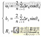
| I. Introduction As the main measurement means of form and position errors, the existing roundness instruments at home and abroad and the form and position error measuring instruments developed on the basis of roundness instruments (such as shape error measuring instruments, shape measurement systems, etc.) can obtain more accurate form and position error measurement results than traditional measuring instruments and measurement methods. However, in the use of these instruments, due to improper adjustment or inappropriate expansion of their scope of use, large measurement errors may occur. In the development of new form and position error measuring instruments, there are also problems such as failure to ensure the manufacturing accuracy and adjustment accuracy of the corresponding components of the instrument according to the design function requirements, or blindly pursuing high manufacturing accuracy, thereby excessively increasing manufacturing costs. This paper analyzes the system error and workpiece installation error of the form and position error measuring instrument, and studies the influence of these error factors on the measurement accuracy of the form and position error, thereby providing a theoretical basis for reducing the measurement cost while ensuring the measurement accuracy and the development of the form and position error measuring instrument. II. System Error Analysis of Form and Position Error Measuring Instrument The existing form and position error measurement system is mainly composed of mechanical part, microcomputer hardware part and measurement software part. To ensure the accuracy of data processing, the measurement software mostly uses double-byte fixed-point number operation or three-byte floating-point number operation method, so the accuracy of the software part is generally not less than 0.01%. The accuracy of the microcomputer hardware part mainly depends on the accuracy of the forward channel. By analyzing the technical characteristics of each part such as the sensor device, amplification and filtering circuit, sampling and holding circuit and A/D analog-to-digital conversion circuit, the limit error of each circuit is obtained, and the Gaussian method is used to synthesize it. It can be seen that the total error value of the hardware device does not exceed 0.2%. Therefore, the microcomputer hardware and software errors of the measuring instrument (excluding the principle error of data processing) are very small and can be ignored. The measurement accuracy of the measuring instrument mainly depends on the accuracy of the mechanical part. 1. The rotation accuracy of the measuring instrument During the rotation process, the relative displacement of the rotation axis to the average position of the axis is the rotation error motion. The error motion causes the rotation axis to move parallel or perpendicular to the axis at each instant. The former is called the end face error motion, and the latter is called the radial rotation error motion. The end face error motion makes the sampling points of the measured workpiece within one rotation not all in one cross section, thereby reducing the correlation between the sampling points. However, since the end face error motion is generally very small, and the actual workpiece surface to be measured is smooth, the probe cannot be in pure point contact when sampling the measured surface, but in small area contact. Therefore, the impact of the end face error motion on the measurement accuracy can be ignored. The rotation accuracy of the rotary table measuring instrument is mainly determined by the rotation accuracy of the measuring instrument spindle, while the rotation accuracy of the center clamping measuring instrument is jointly determined by the center accuracy of the measuring instrument and the shape accuracy of the center hole of the measured workpiece. The radial rotation error δr will be directly transmitted to the sampling data Δri (i = 1, 2, 3...n), thereby affecting the calculation accuracy of the least squares center coordinates. The expression of the least squares center coordinates is [1]
2. Axial guide rail straightness error (1) Axial guide rail straightness error in the plane where the axis of rotation is located This error will be reflected in the measurement result at a ratio of 1:1. However, for the sampling data of the same section, it is equivalent to only a fixed error ΔSr. If the sampling method of even-numbered points with equal intervals is adopted, it can be known from formula (1) that
(2) Guide rail straightness error perpendicular to the plane where the axial guide rail and the rotation axis are located This error ΔShj will cause the probe to deviate from the radial direction, as shown in Figure 1, so that the measured radius increment is
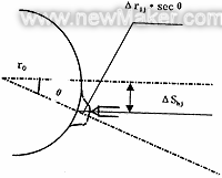
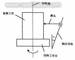
As analyzed in the previous section, the parallelism error perpendicular to the plane where the axial guide rail and the rotary axis are located is a non-sensitive error and can be ignored. The following only analyzes the influence of the parallelism error in the plane where the axial guide rail and the rotary axis are located. When the rotary axis of the measuring instrument is not parallel to the axial movement direction of the probe, its parallelism error will be repeatedly reflected in the sampling data at a ratio of 1:1. As shown in Figure 2, assuming that the angle between the guide rail and the rotary axis is α, and the section spacing is Z, then the compression of the probe on the kth section is Δrz=kZtgα. Obviously, this parallelism error is a linear system error, and for the sampling data of the same section, it is equivalent to a fixed error ΔSk, which will not change the position of the section center coordinates. Therefore, for measuring instruments that use data processing software that meets the corresponding error definition, this error only affects the cylindrical error evaluation result, and will not affect the measurement accuracy of roundness, coaxiality, axis and element line straightness errors[2,3].
If the actual deviation of each sampling point from the least square circle is εij, then [1]
Similarly, ignoring d(Δrij), substituting equation (9) into equation (7) yields
3. Workpiece installation error analysis The installation error of the workpiece includes the installation eccentricity error and the installation tilt error. 1. Workpiece installation eccentricity error When the analytical evaluation method is used to solve the form and position error, the error caused by the installation eccentricity e on the polar diameter at each sampling point is [1]
When a traditional roundness meter that records contour graphs is used for measurement, the image distortion error caused by the installation eccentricity e is [4]
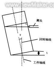
2. Workpiece installation tilt error The verticality error of the workpiece installation base surface to the axis or the presence of foreign matter between the workpiece installation base surface and the worktable surface will cause the workpiece installation tilt error. For the convenience of analysis, it is assumed that the workpiece is an ideal cylinder with a diameter of 2R, and the inclination angle of its axis to the rotation axis is γ, as shown in Figure 3. Due to the inclination of the workpiece, the profile of its measured cross-section is an ellipse, and the major and minor axes of the ellipse are 2Rsecγ and 2R respectively. The measurement error caused by the inclination of the workpiece installation is δt=R(secγ-1). If the installation inclination height difference t=0.1mm, R=25mm, then γ=0.115°, δt=0.05μm. Therefore, under the condition of ensuring that the inclination of the workpiece is small, δt can be ignored.
Therefore, for measuring instruments that use analytical evaluation data processing software, the workpiece installation inclination error has little effect on the form and position error evaluation results and can be ignored; but for traditional roundness instruments that use the recorded contour image evaluation method, the recorded contour image is F = M2R (secγ-1), which shows that the workpiece installation inclination error has a greater impact on the measurement results, especially this inclination error will also affect the center position of the recorded contour of each sampling section, so it has a greater impact on the measurement results of various form and position errors. 4. Conclusion The accuracy of form and position error measuring instruments mainly depends on the accuracy of the mechanical part, among which the rotation accuracy is the most important accuracy indicator; the straightness error of the axial guide rail will affect the evaluation results of the cylindrical error and the element line straightness error of the measured workpiece; the parallelism error of the axial guide rail to the rotation axis mainly affects the measurement accuracy of the cylindrical error. (end) |
Previous article:Development of non-contact robot measurement and control system
Next article:Crankshaft connecting rod 120° phase angle measurement fixture
- Keysight Technologies Helps Samsung Electronics Successfully Validate FiRa® 2.0 Safe Distance Measurement Test Case
- From probes to power supplies, Tektronix is leading the way in comprehensive innovation in power electronics testing
- Seizing the Opportunities in the Chinese Application Market: NI's Challenges and Answers
- Tektronix Launches Breakthrough Power Measurement Tools to Accelerate Innovation as Global Electrification Accelerates
- Not all oscilloscopes are created equal: Why ADCs and low noise floor matter
- Enable TekHSI high-speed interface function to accelerate the remote transmission of waveform data
- How to measure the quality of soft start thyristor
- How to use a multimeter to judge whether a soft starter is good or bad
- What are the advantages and disadvantages of non-contact temperature sensors?
- Innolux's intelligent steer-by-wire solution makes cars smarter and safer
- 8051 MCU - Parity Check
- How to efficiently balance the sensitivity of tactile sensing interfaces
- What should I do if the servo motor shakes? What causes the servo motor to shake quickly?
- 【Brushless Motor】Analysis of three-phase BLDC motor and sharing of two popular development boards
- Midea Industrial Technology's subsidiaries Clou Electronics and Hekang New Energy jointly appeared at the Munich Battery Energy Storage Exhibition and Solar Energy Exhibition
- Guoxin Sichen | Application of ferroelectric memory PB85RS2MC in power battery management, with a capacity of 2M
- Analysis of common faults of frequency converter
- In a head-on competition with Qualcomm, what kind of cockpit products has Intel come up with?
- Dalian Rongke's all-vanadium liquid flow battery energy storage equipment industrialization project has entered the sprint stage before production
- Allegro MicroSystems Introduces Advanced Magnetic and Inductive Position Sensing Solutions at Electronica 2024
- Car key in the left hand, liveness detection radar in the right hand, UWB is imperative for cars!
- After a decade of rapid development, domestic CIS has entered the market
- Aegis Dagger Battery + Thor EM-i Super Hybrid, Geely New Energy has thrown out two "king bombs"
- A brief discussion on functional safety - fault, error, and failure
- In the smart car 2.0 cycle, these core industry chains are facing major opportunities!
- The United States and Japan are developing new batteries. CATL faces challenges? How should China's new energy battery industry respond?
- Murata launches high-precision 6-axis inertial sensor for automobiles
- Ford patents pre-charge alarm to help save costs and respond to emergencies
- New real-time microcontroller system from Texas Instruments enables smarter processing in automotive and industrial applications
- (Bonus 3) GD32L233 Review - Unboxing and showing off the big box
- CPLD
- Help, after the load power supply has been working for a period of time, the microcontroller will shut down automatically
- The silk screen is AA6B SOT23-6 package with 2.2UH inductor 3.7~4.2V boost to 5V
- Add uart6 driver
- How fast can electric vehicles be “fast charged”?
- 5G millimeter wave RF algorithm technology
- Share NFC universal card reader circuit diagram
- SAM-L10-L11 series Questions and Answers
- LC filter design issues in DCDC step-down circuits

 (1)
(1)

 (4)
(4)


 (9)
(9)


 Introduction to Artificial Intelligence and Robotics (Murphy)


 京公网安备 11010802033920号