1 Principle and composition of micro-ranging radar
1.1 Ranging Method
There are three common radar ranging methods: pulse ranging, frequency modulated continuous wave ranging, and phase ranging. The first two are commonly used. The pulse ranging resolution must be less than 1 m, and the pulse width must be less than 6.67 ns. Even if pulse radars generally use pulse compression, it is quite difficult to achieve centimeter-level accuracy, not to mention that it is difficult to achieve in circuits at the cost of increasing the receiver bandwidth and reducing the receiving sensitivity. Therefore, for more accurate distance measurement, the frequency modulated continuous wave ranging method is generally used.
There are two types of FM continuous wave ranging: triangle wave modulation and sine wave modulation. Here we choose triangle wave modulation.
In triangle wave modulation, the ranging formula is:
Where: R is the distance; c is the speed of light;
is the difference between the positive transmitting frequency and the receiving frequency of the triangle wave, fb- is the difference between the negative transmitting frequency and the receiving frequency of the triangle wave; f is the modulation frequency of the triangle wave; △fm is half of the maximum frequency deviation of the modulated transmitting frequency.
The choice of triangular wave modulation frequency is related to the distance resolution. If f=200 Hz, △fm=100 MHz, and the measured frequency fbav is 50 kHz, then R≈93.750 0 m can be calculated; if the measured frequency fbav=50.001 kHz, R=93.751 8 m, the difference between the two is 1.8 mm, that is, every 1 Hz represents a distance of 1.8 mm. The resolution can be increased by increasing the value of the modulation frequency f. If f=1 000 Hz, other parameters remain unchanged, the measured frequency fbav=50 kHz, R=18.750 O m; fbav=50.001 kHz, R=18.750 4 m, the difference is 0.4 mm, and every 1 Hz represents a distance of 0.4 mm.
If it is a moving target, according to the speed measurement formula:
Find the speed of the moving target. Where V is the radial speed of the target and λ is the wavelength of the emitted microwaves. Of course, the values of fb+ and fb- for a fixed target are equal.
1.2 Composition
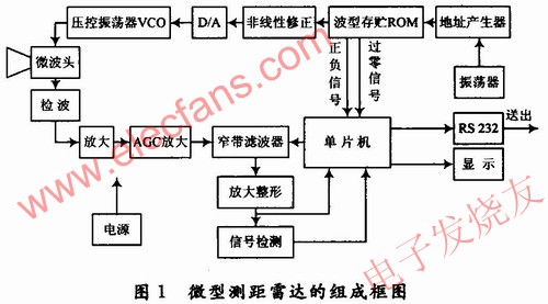
According to the radar principle of triangle wave modulation, there must first be a microwave head. The microwave head can be based on the speed measurement microwave head, and the body effect oscillator is added with a varactor tube to change to a voltage-controlled oscillation, and directly mix the frequency. At the same time, a triangle wave generator is also required. In order to correct the nonlinearity of the voltage-controlled oscillator and make its frequency change linearly, nonlinear correction must be performed.
To enhance the effect, an analog filter bank can be used for accumulation processing. Of course, the analog signal can also be converted into a digital signal by high-speed A/D sampling and then processed by DSP, but the cost is higher.
Compared with industrial computers and PC104 modules, the single-chip control circuit is simpler and less expensive. Since there are no complex calculations, the speed can fully meet the requirements.
This design consumes less power and can meet the power supply requirements with batteries.
The block diagram of the micro-ranging radar is shown in Figure 1.

1.3 Working Principle
The triangle wave modulation frequency is selected as 200 Hz, D/A is selected as 12 bits, ROM is 16-bit data output, and 12-bit data is used as D/A input; one bit is used as a pulse output when the positive and negative slopes of the triangle wave change, the positive slope is "1", and the negative slope is "0"; the other bit is used as a zero-crossing signal during a triangle wave cycle, and is sent to the interrupt INT0 of the microcontroller. When the positive and negative slopes of the triangle wave change, a pulse signal is output. After the microcontroller generates a zero-crossing interrupt, the positive and negative signals are judged. If it is "1", fb+ is obtained; if it is "0", fb- is obtained.
When the radar is working, the microcontroller controls the narrowband filter to scan continuously. When a certain filter has a signal, the output of the signal detection circuit composed of a re-triggerable monostable circuit changes from "0" to "1". The microcontroller obtains the frequency in the band according to the output of the narrowband filter, determines the distance range with low accuracy, and uses the amplified shaping output to count or measure the pulse cycle to obtain a sufficiently accurate frequency value, which is the accurate distance. R and V are calculated according to the formula and sent to the display for display, or sent to the upper-level computer system through the RS 232 serial port.
2 Composition of each part
2.1 Microwave head
The microwave head includes a horn antenna, a bulk effect oscillator, a circulator, and a mixer. The bulk effect oscillator generates and transmits microwaves, the horn antenna is used for external microwave transmission and reception, the circulator isolates the transmission and reception, and the mixer extracts the difference between the transmission frequency and the reception frequency. The microwave heads commonly used abroad are 24 GHz, 35 GHz, and 77 GHz, and the products of Wisewave can be used. Its power output is +10 dBm, the frequency deviation DC is 100 MHz, the beam width is 120, and it is circularly polarized. [page]
2.2 Triangle Wave Generator
The triangle wave generator is digitally formed. The D/A is 12 bits. To generate a modulation frequency of 200 Hz, the oscillator is about 0.819 2 MHz. Considering that the frequency of a general crystal is in the MHz range, the address generator is a 13-bit counter, 74HC4040 is selected, and the counter does not use the lowest bit, then the oscillator frequency is 200 Hz×212×2=1.638 4 MHz. A TTL gate circuit can be used as an oscillator. This design uses 74HC04.
The waveform storage uses the E2PROM chip AT28C64, and the crystal uses 1.683 4MHz. The most important point is that the nonlinear curve of the microwave head must be measured so that the correction data can be loaded into the nonlinear correction ROM. For simplicity, the correction data can be burned in the waveform storage ROM without adding a dedicated nonlinear correction circuit.
2.3 Narrowband Filter
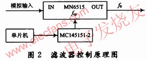
The development and integration of analog devices provide sufficient conditions for miniaturization. For example, Panasonic's MN6515 has only 8 pins. The center frequency f0 of its bandpass filter can be controlled by the external clock frequency fcp, and the ratio fcp/f0 is about 15.7. As long as the value of fcp is changed, the center frequency of the bandpass filter will move within the range of 0 to 32 kHz, which is very convenient and can be controlled using the method shown in Figure 2.

There is also a narrowband filter MAXIM's MAX262, which controls the values of f0 and Q by coding input. There are 64-order filters and 128-level Q value control. At the same time, the oscillation frequency can also be controlled. It is composed of multiple MAX262 chips, so that the order of the narrowband filter can reach hundreds or even thousands. By controlling the difference in Q value, the 3 dB bandwidth of the narrowband filter can be designed to be the same or similar width from the low end to the high end of the frequency.
2.4 Amplification and AGC Amplification Circuit
The pre-amplifier circuit can use low-noise operational amplifiers from various companies, the AGC circuit can use AD603 from AD, or VGA610 from BB, and the amplifier and shaping circuit can use the new R~R output operational amplifiers from TI or other companies.
2.5 Microcontroller
The single-chip microcomputer uses AT89C51 from Atmel, and other single-chip microcomputers such as PIC or AVR series can also be used. These single-chip microcomputers are low-cost and commonly used by people.
3 Software components
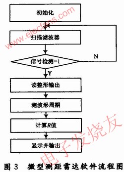
The software is written in assembly language, and the flow chart is shown in Figure 3.

4 Conclusion
The low-cost micro-range radar is feasible in principle after experiments, but the distance is short. After actual testing, it was found that the microwave head uses direct mixing to output low sensitivity. The next step of improvement requires adding an intermediate frequency, demodulating after amplification, and then performing video amplification.
For radars that require longer range, the method of increasing the transmit power and the antenna area can be used. When the power is large, considering the influence of continuous wave radar leakage, the transmit antenna and the receive antenna need to be separated. For closer distance measurements, such as less than 2 to 3 meters, ultrasonic measurement can be used. The use of micro-range radar is very broad, and it will be widely used in many civilian fields in the future.
Previous article:Design of offshore earthquake detection transmission system
Next article:Design of low-cost micro-range radar
- Popular Resources
- Popular amplifiers
- Keysight Technologies Helps Samsung Electronics Successfully Validate FiRa® 2.0 Safe Distance Measurement Test Case
- From probes to power supplies, Tektronix is leading the way in comprehensive innovation in power electronics testing
- Seizing the Opportunities in the Chinese Application Market: NI's Challenges and Answers
- Tektronix Launches Breakthrough Power Measurement Tools to Accelerate Innovation as Global Electrification Accelerates
- Not all oscilloscopes are created equal: Why ADCs and low noise floor matter
- Enable TekHSI high-speed interface function to accelerate the remote transmission of waveform data
- How to measure the quality of soft start thyristor
- How to use a multimeter to judge whether a soft starter is good or bad
- What are the advantages and disadvantages of non-contact temperature sensors?
- Innolux's intelligent steer-by-wire solution makes cars smarter and safer
- 8051 MCU - Parity Check
- How to efficiently balance the sensitivity of tactile sensing interfaces
- What should I do if the servo motor shakes? What causes the servo motor to shake quickly?
- 【Brushless Motor】Analysis of three-phase BLDC motor and sharing of two popular development boards
- Midea Industrial Technology's subsidiaries Clou Electronics and Hekang New Energy jointly appeared at the Munich Battery Energy Storage Exhibition and Solar Energy Exhibition
- Guoxin Sichen | Application of ferroelectric memory PB85RS2MC in power battery management, with a capacity of 2M
- Analysis of common faults of frequency converter
- In a head-on competition with Qualcomm, what kind of cockpit products has Intel come up with?
- Dalian Rongke's all-vanadium liquid flow battery energy storage equipment industrialization project has entered the sprint stage before production
- Allegro MicroSystems Introduces Advanced Magnetic and Inductive Position Sensing Solutions at Electronica 2024
- Car key in the left hand, liveness detection radar in the right hand, UWB is imperative for cars!
- After a decade of rapid development, domestic CIS has entered the market
- Aegis Dagger Battery + Thor EM-i Super Hybrid, Geely New Energy has thrown out two "king bombs"
- A brief discussion on functional safety - fault, error, and failure
- In the smart car 2.0 cycle, these core industry chains are facing major opportunities!
- Rambus Launches Industry's First HBM 4 Controller IP: What Are the Technical Details Behind It?
- The United States and Japan are developing new batteries. CATL faces challenges? How should China's new energy battery industry respond?
- Murata launches high-precision 6-axis inertial sensor for automobiles
- Ford patents pre-charge alarm to help save costs and respond to emergencies
- The experience and IQ of the elderly are not proportional
- Summary of filter reliability test items, a must for designers!
- [GD32E231 DIY Contest] Part 3: Submit videos and documents
- Please make ST's hal library more rigorous!!!
- FeatherSnow can run CircuitPython or Arduino
- Passive high-pass filter circuit has no output
- Will there be any impact if the amplifier circuit is not zeroed? @【Analog Electronics】
- What is the difference between automotive electronics and other electronics?
- Allwinner V853 heterogeneous core impression
- I have designed a switching power supply that converts AC220V to DC5V/A. What tests do I need to do to make it a qualified power supply?

 LTC2057HVHDD#PBF


 京公网安备 11010802033920号